Resolving Interference in a Crowded Wi-Fi Environment Using BAW Filters (Part 2)
January 30, 2018
This is the second blog post in a 2-part series looking at design challenges for Wi-Fi front-end designs. Part 1 covered thermal considerations.
There are any number of strategies that consumers can try to fix interference problems with Wi-Fi in their homes — moving the router, reconnecting the device to their Wi-Fi network, power cycling the modem … and calling their service provider when nothing works and they don’t know what else to try. But as an RF engineer, how can you design a Wi-Fi access point that addresses the biggest interference issues from the outset?
This blog post examines the following factors that can impact Wi-Fi interference:
- The need to support multiple wireless standards
- Different types of interference
- Why band edges matter
- The importance of high-performance bandedge and coexistence BAW filters
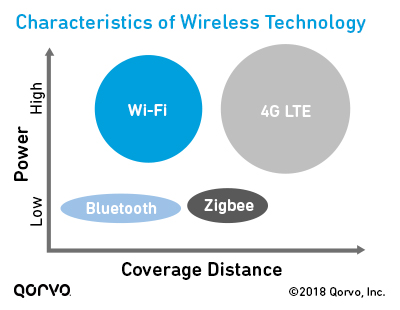
One access point, many standards
When developing Wi-Fi access points, designers must consider many wireless technology standards:
- Standards that operate at short and mid coverage ranges, such as Bluetooth, Zigbee and Z-Wave
- Standards that operate at higher power levels and short and long ranges, including Wi-Fi, 3G/4G LTE and 5G
Many of these standards can interfere with each other, leading to
connectivity problems for users.
And then there’s unlicensed spectrum to contend with. Licensed and unlicensed networks are becoming more important factors as constrained wireless communications offload data to continually expand capacity. Also, the new Internet of Things (IoT) realm draws heavily on this unlicensed spectrum.
The challenge is to keep all these licensed and unlicensed bands and
multiple protocols working in conjunction with each other without interference
difficulties.
Different types of interference: From in-device to LTE and Bluetooth
Interference can occur within a device or between devices, including between wireless carrier signals or between wireless standards. The most common interference scenario is Bluetooth and LTE with Wi-Fi because these technologies are so widespread. Let's look at some of these in more detail.
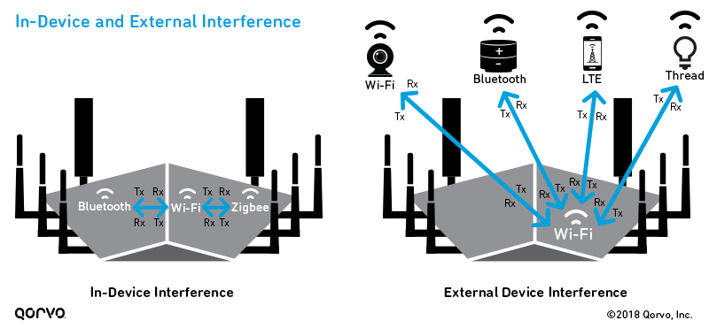
- In-device coexistence: For in-device coexistence, the system’s multiple antenna architectures can interfere with each other. As a result, the coupling between the affected antennas (antenna isolation) is compromised. The foreign transmit (Tx) signal increases the noise power at the affected receiver, which has a negative impact on the signal-to-noise ratio. The receive (Rx) sensitivity decreases, which causes what engineers call “desensitization.”
Desensitization is a degradation of the sensitivity of the receiver due to external noise sources, and results in dropped or interrupted wireless connections. It isn't a new problem — early radios encountered receiver sensitivity when other components became active — but now it’s particularly troublesome for today’s wireless technologies, including smartphones, Wi-Fi routers, Bluetooth speakers and other devices.
The primary “desense” scenarios are:
- Two radio systems occupy bordering frequencies, and carrier leakage occurs.
- The harmonics of one transmitter fall on the carrier frequencies used by another system.
- Two radio systems share the same frequencies.
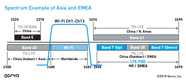
- LTE and Wi-Fi: As shown in the below figure, several LTE bands — Bands 40, 7 and 41 — are very close to the Wi-Fi band channels. Leakage into the adjacent Wi-Fi radio band is very probable at both the high and low end of the 2.4 GHz band. Without proper system design, the cellular and Wi-Fi channels 1 and 11 can interfere with each other's transmissions and receive capability.
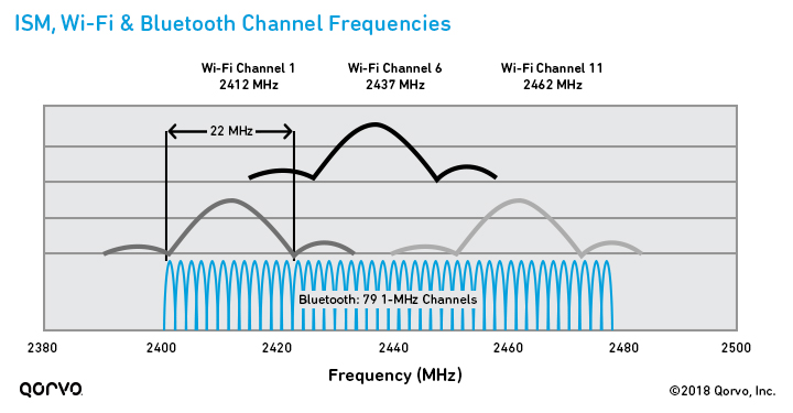
- Bluetooth and Wi-Fi: Bluetooth and Wi-Fi transmit in different ways using differing protocols, but they operate in the same frequency ranges, as shown in the following figure. As a result, when Wi-Fi operates in the 2.4 GHz band, Wi-Fi and Bluetooth transmissions can interfere with each other. Because Bluetooth and Wi-Fi radios often operate in the same physical area (such as inside an access point), interference between these two standards can impact the performance and reliability of both wireless interfaces.
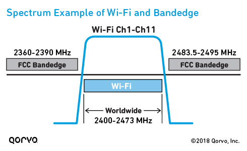
Why band edges matter for Wi-Fi coexistence
One way federal governments have tried to help consumers is by regulating the emissions and spectrum of many electronic devices and requiring consumer products to undergo compliance testing.
In the United States, the Federal Communications Commission (FCC) requires that most RF devices undergo testing to demonstrate compliance to FCC rules. They enforce strict band edges by requiring steep skirts on the lower and upper Wi-Fi frequencies, to help with coexistence with neighboring spectrum.
There are two ways for Wi-Fi access points to meet this FCC requirement:
- Back off the power level on Wi-Fi channel 1 and 11, because they're at the edge of the Wi-Fi spectrum.
- Use filters with very steep band edges.
Design tips to overcome interference challenges: Use high-Q BAW filters
Our approach is to use high-performance coexistence and bandedge filters, to allow Wi-Fi transmitters to operate close to the upper and lower FCC band edges.
Customers have had success using high-Q bulk acoustic wave (BAW) bandpass filters, which offer many advantages:
- Extremely steep skirts that simultaneously exhibit low loss in the Wi-Fi band and high rejection in the band edge and adjacent LTE/TD-LTE bands
- Significant size reductions, which aid designers in creating smaller, more attractive end-user devices for homes and office environments
- Resolves coexistence of Wi-Fi and LTE signals within the same device or near one another
- Unique power handling capabilities, allowing for implementation into high-performance, high-power access points and small cell base stations
These filters address the stringent thermal challenges
of multi-user multiple-input/multiple-output (MU-MIMO) systems, without
compromising harmonic compliance and emissions performance. This is critical
to achieving reliable coverage across the full allocated spectrum.
But why do high-Q BAW filters make such a difference for FCC band edges?
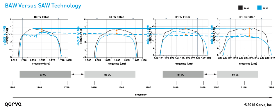
#1: BAW devices have lower insertion loss, steeper band edges and better temperature stability than SAW technology at Wi‑Fi frequencies
As you move into higher bandwidths like Wi-Fi, surface acoustic wave (SAW) devices can suffer from higher insertion losses than BAW due to radiation of acoustic energy into the bulk of the substrate. As shown in the following figure, as you move up (to the right) in frequency, you can see high-Q BAW is a good option for filter designs due to this bulk radiation loss effect. Also, BAW maintains the steep skirts required for FCC band edges; SAW can’t meet the performance requirements at these higher frequencies.
BAW also has better temperature stability than other technologies, which gives it an advantage during FCC certification tests. Most Wi-Fi designs are created at room temperature (20-25°C) on a bench, but the system in its application environment can actually operate around 60-80°C. Insertion loss increases as temperature increases, and failing to estimate for this can cause issues during product certification. Using BAW reduces the shifts in insertion loss and makes certification test results more predictable.
Learn more about BAW versus SAW in our free e-book, RF Filter Technologies For Dummies® (Volume 1).
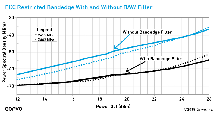
#2: BAW filtering can help engineers provide seamless transitioning between interfering bands
As shown in the following figure, the bandedge response is better using a filter than without it, and it allows designers to push the limit on RF front-end output power while meeting the FCC requirement for power spectral density. This means bandedge BAW filtering allows operators and manufacturers to deliver high-speed data and greater bandwidth by using spectrum that might be lost with no filtering.
#3: High-Q BAW bandedge filters can extend the range in channel 1 and 11 by 2-3 times
Wi-Fi designers normally must set the entire unit power to whatever the lowest bandedge-compliant power is for all channels. So, if the compliant channel at channel 1 is 15 dBm but channel 6 can achieve 23 dBm, the designer settles the entire power control scheme to 15 dBm. Using bandedge filtering allows designers to set the power scheme to much higher powers, thus making it possible to use fewer RF chains to achieve their goals.
BAW bandedge filters can also exhibit power handling capabilities for transmitting up to 28 dBm. This can improve system performance by greater than 15 percent and enable 5G multi-MIMO with less co-channel interference.
CPE developers who don’t use bandedge filtering have difficulty meeting FCC requirements on Wi-Fi band channels 1 and 11. In contrast, when high-Q BAW bandedge filters are used, it allows the CPE designer to keep the power level the same throughout all the channels (1 – 11).
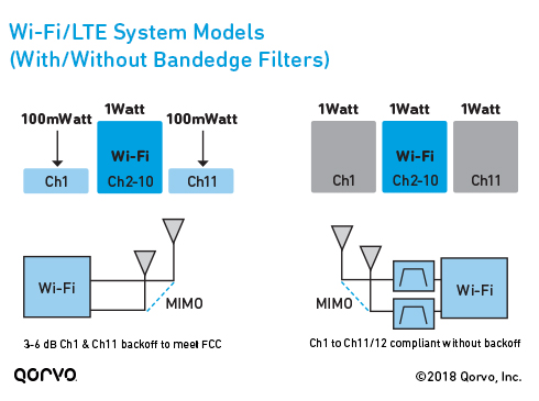
To paint the picture, here’s the difference in user experience with and without bandedge filters:
- Without bandedge filters: Let’s assume you’re in a house with several individuals using Wi-Fi and mobile phones. You’re on Wi-Fi using channel 5, streaming a football game and experiencing no buffering or interruption. But then new mobile users arrive in the house and begin to take over your channel 5 Wi-Fi space. The CPE unit adjusts and bounces you to channel 1 to free up more space on channel 5. If the Wi-Fi unit doesn't have bandedge filters (as in the block diagram on the left), your Wi-Fi strength and streaming degrade to the point where buffering occurs. Why? Because to meet the FCC requirement, the CPE unit must back off its power in channel 1 so it doesn't interfere with adjacent cellular bands.
- With bandedge filters: However, if the CPE unit had been designed with bandedge filters (as shown in the block diagram on the right), channel 1 and 11 would not be compromised and the power level would not require backoff. You can watch your streamed football game without any buffering.
Go in depth: How Qorvo Wi-Fi solutions can help solve interference challenges
In a connected world with more and more devices and wireless standards, coexistence and interference issues will not go away. To make use of every bit of spectrum available, Wi-Fi designs with high-Q BAW filters can improve the performance of Wi-Fi access points.
Learn more in this detailed Chalk Talk video (37:56), sponsored by Mouser Electronics and Qorvo, how Qorvo technology can help you achieve a Wi-Fi product that mitigates these coexistence and bandedge challenges.
Did you miss part 1 in
our Wi-Fi connectivity series? Read our top tips for overcoming
thermal challenges in Wi-Fi access points.

"Chalk Talk" with Qorvo: Wi-Fi Connectivity (37:56). Watch Now >
Have another topic that you would like Qorvo experts to cover? Email your suggestions to the Qorvo Blog team and it could be featured in an upcoming post. Please include your contact information in the body of the email.