4 Things to Know About Antenna Tuning in 4G / 5G Smartphones
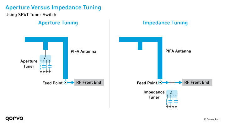
Today, aperture tuning is the primary method used in handsets to overcome
reduced antenna area and efficiency. Midtier and higher-end smartphones use a
combination of aperture and impedance tuning to support the ever-broadening
range of frequency bands — especially for 5G.
#2: How to choose the right tuning components
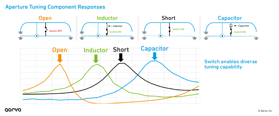
Adding tuning components like a capacitor or inductor between the switch and the radiating element can help further adjust the resonant frequency to support LTE and 5G bands. The image below shows the resonant frequency of an antenna when the switch is off, when it is on, and when an inductor or capacitor is inserted into the circuit.
It’s important to choose aperture tuning switches, capacitors and inductors with the best performance. Some guidelines include the following:
Tuner Switches:
- Use switches with low RON and COFF to minimize loss in the system.
- Use high-linearity tuner switches to avoid impact on radiated spurious emissions (RSE) and TIS.
- Switches must be multimode for tuning 2G/3G/4G/5G standard frequency ranges.
- Switches should be capable of handling high RF voltages for broadband antenna applications.
Tuning Components:
- Use capacitors with a capacitance value greater than 0.5 pF to avoid using a component with high tolerances.
- Avoid using inductors with an inductance value greater than
36 nH.
#3: RON, COFF and removing unwanted resonance
Two critical characteristics of aperture tuning switches significantly affect antenna efficiency: on resistance (RON) and off capacitance (COFF). Aperture switches are capacitive in their OFF (COFF) state, and they’re resistive in their ON (RON) state. If an inductor is connected to the RF port for tuning, then the combination of COFF and inductance will cause unwanted resonances. In other words, when the switch is in the OFF state, the resonance mechanism is destined to exist. To suppress this resonance, tuner switches have an internal switch to shunt to ground.
The next figure shows an SP4T tuner switch that is connected between an antenna and tuning elements, to tune the antenna to different frequency bands. The antenna is connected to a tuning capacitor via the RF3 port, whereas the other three ports are switched OFF. The ON state resistance between the antenna and RF3 port is replaced with RON, and the parasitic OFF state capacitance between the antenna and RF1, RF2 and RF4 ports is emulated using COFF. This ground path capability helps eliminate the resonances caused by the capacitances generated from the off-switch ports. In the image below, on the bottom right, the black line shows resonance, while the orange line shows no resonance.