You’ve Got the Power: 6 Essentials for Brushless DC Motor Control

February 11, 2021

Consumer demands for more power, reliability, functionality, and performance are shaping the rapid evolution of electronic devices – from lawnmowers, refrigerators, vacuums, automobiles and more. And manufacturers are eager to deliver on all fronts. Motor control plays a chief role in making good on these promises, and understanding the fundamentals is the first step to getting there.

This post includes excerpts from our newly developed Motor Control Fundamentals For Dummies book, providing the key elements of motor control for brushless DC (BLDC) motor management and how it improves efficiency while reducing cost, saving space, and increasing performance. You can download the full book within the E-Book section in Qorvo’s Design Hub.


Here are some highlights from the E-Book:

  1. The Different Motor Types

Today there are several types of motor control topologies available: brushed, brushless DC (BLDC), stepper and induction. The two most closely related brushless motor types are BLDC and permanent magnet synchronous motors (PMSMs).

 

Motor Control Fundamentals For Dummies

Motor Control Fundamentals For Dummies

Download the E-Book

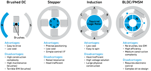
Brushless motors have become very popular for many of today’s applications because they eliminate the need for motor brushes. These BLDC topologies use commutation logic to move the rotor, making them more efficient and reliable.
 

Motor_Control_Image_1.png


Commutation in a brushed motor is produced by the brush/commutator interface. This interface causes friction and arcing, which over time degrades the brushes. This friction causes heat and a reduction in motor life.

BLDC motors have many advantages over brushed motors. They are energy efficient, smaller, lighter, quieter, more reliable and more durable. Moreover, they offer precise speed control and are better for variable-speed applications.
 

2. Understanding BLDC and PMSM Type Motors

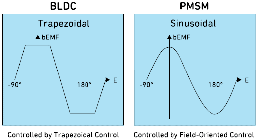
BLDC and PMSM motors work on the principle of a synchronous motor. The rotor continues to pursue the stator at every commutation, so the motor continuously moves. However, these two DC-type motors have a different geometry of their stator winding, therefore, they produce different back-electromotive force (BEMF) responses. The BLDC BEFM is trapezoidal. The PMSM motor has a sinusoidal BEMF, so the coil windings are wound in a sinusoidal fashion. To maximize performance, these motors generally use sinewave commutation.


Motor_Control_Image_2.png

BLDC and PMSM motors generate BEMF by their windings when operated. In any motor, because of motion, the EMF produced is known as back-EMF (BEMF) because the EMF induced in the motor opposes the EMF of the generator.
 

3. An Explaination of Field-Oriented Control

To achieve the sinusoidal waveform that controls the PMSM motor, a field-oriented control (FOC) algorithm is required. FOC is typically used to maximize the efficiency of the PMSM three-phase motor. The sinusoidal controller for the PMSM is more complex and costlier than the BLDC trapezoidal controller. However, this cost increase has advantages like lower noise and less harmonics in the current waveform. The main advantage of the BLDC is it’s easier to control. Ultimately, the choice of which motor is best depends on its application.
 

4. Sensored and Sensorless BLDC and PMSM motors

BLDC and PMSM motors can be sensored or sensorless. Sensored motors are used in applications requiring the motor to start up under a load condition. They use Hall sensors, which are embedded into the motor stator. The sensor is essentially a switch with a digital output equal to the sensed magnetic field polarity. The motor requires a separate Hall sensor for each phase. Therefore, a three-phase motor requires three Hall sensors. Sensorless motors require algorithms to operate using the motor as the sensor. They rely on BEMF information. By sampling the BEMF, the rotor position can be deduced, eliminating the need for hardware-based sensors. Regardless of motor topology, controlling these machines requires knowing the rotor position so the motor can be efficiently commutated.
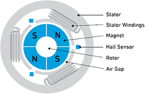
Motor with Hall Sensors
 

5. Motor Control Software Algorithms

Today, software algorithms (i.e., a set of instructions designed to perform a specific task), like computer programs, are used to control BLDC and PMSM motors. These software algorithms improve efficiency and reduce operating costs by monitoring and controlling motor operations. Some of the primary functions of algorithms are motor initialization, Hall sensor rotor position detection, and switch signal checking for increasing or decreasing the current reference.
 

6. How Controllers Process Motor Sensor Information

A three-phase BLDC motor has six states. As shown in the figure below, a three-bit code can be used to represent an opcode number between 1 and 6. The sensors are placed to provide a three-bit data output using six of the eight opcodes (1 through 6). This information is useful because the controller can determine when an illegal opcode has been issued and act on the legal opcodes (1 through 6). As shown below, the algorithm obtains the Hall sensor opcode and decodes it. When the Hall sensor opcode changes in value, the controller changes the energization scheme to achieve commutation. The microcontroller uses the opcode to extract energization information from the lookup table. After the three-phase inverter is energized with the new sector command, the magnetic field moves to the new position, pushing the rotor along with it. This process repeats endlessly while the motor operates.
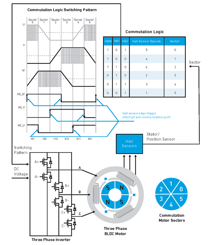
Block Diagram of Commutation Logic Functionality
 

The above is just a brief excerpt from the Motor Control For Dummies from Qorvo. We encourage you to download our free e-book for more insights into power management.

Stay up to date with us.

Sign up for notification on new products, product/process change notifications (PCNs) and end of life (EOL) alerts.

Sign Up

Qorvo products are at work connecting, protecting and powering the planet. We bring core radio frequency (RF) and power technologies and solutions to automotive, consumer, defense & aerospace, industrial & enterprise, infrastructure and mobile markets.

Stay Connected

  • Facebook
  • X
  • LinkedIn
  • YouTube
  • Products
  • Solutions
  • Design Hub
  • New Products
  • Product Compliance
  • Blog Posts
  • Events & Trade Shows
  • News Releases
  • Success Stories
  • Technical Articles
  • About Us
  • Careers
  • Corporate Videos
  • Quality
  • Locations
  • Investors
  • How to Buy
  • Forums
  • Portals
  • Contact Us
  • Subscription Center
Site MapFeedbackLegalPrivacySupply Chain Transparency

© 2026 Qorvo US, Inc

|

+1-833-641-3810

You’ve Got the Power: 6 Essentials for Brushless DC Motor Control

February 11, 2021

Consumer demands for more power, reliability, functionality, and performance are shaping the rapid evolution of electronic devices – from lawnmowers, refrigerators, vacuums, automobiles and more. And manufacturers are eager to deliver on all fronts. Motor control plays a chief role in making good on these promises, and understanding the fundamentals is the first step to getting there.

This post includes excerpts from our newly developed Motor Control Fundamentals For Dummies book, providing the key elements of motor control for brushless DC (BLDC) motor management and how it improves efficiency while reducing cost, saving space, and increasing performance. You can download the full book within the E-Book section in Qorvo’s Design Hub.


Here are some highlights from the E-Book:

  1. The Different Motor Types

Today there are several types of motor control topologies available: brushed, brushless DC (BLDC), stepper and induction. The two most closely related brushless motor types are BLDC and permanent magnet synchronous motors (PMSMs).
 

Motor Control Fundamentals For Dummies

Motor Control Fundamentals For Dummies

Download the E-Book

Brushless motors have become very popular for many of today’s applications because they eliminate the need for motor brushes. These BLDC topologies use commutation logic to move the rotor, making them more efficient and reliable.


Motor_Control_Image_1.png


Commutation in a brushed motor is produced by the brush/commutator interface. This interface causes friction and arcing, which over time degrades the brushes. This friction causes heat and a reduction in motor life.

BLDC motors have many advantages over brushed motors. They are energy efficient, smaller, lighter, quieter, more reliable and more durable. Moreover, they offer precise speed control and are better for variable-speed applications.
 

2. Understanding BLDC and PMSM Type Motors

BLDC and PMSM motors work on the principle of a synchronous motor. The rotor continues to pursue the stator at every commutation, so the motor continuously moves. However, these two DC-type motors have a different geometry of their stator winding, therefore, they produce different back-electromotive force (BEMF) responses. The BLDC BEFM is trapezoidal. The PMSM motor has a sinusoidal BEMF, so the coil windings are wound in a sinusoidal fashion. To maximize performance, these motors generally use sinewave commutation.


Motor_Control_Image_2.png

BLDC and PMSM motors generate BEMF by their windings when operated. In any motor, because of motion, the EMF produced is known as back-EMF (BEMF) because the EMF induced in the motor opposes the EMF of the generator.
 

3. An Explaination of Field-Oriented Control

To achieve the sinusoidal waveform that controls the PMSM motor, a field-oriented control (FOC) algorithm is required. FOC is typically used to maximize the efficiency of the PMSM three-phase motor. The sinusoidal controller for the PMSM is more complex and costlier than the BLDC trapezoidal controller. However, this cost increase has advantages like lower noise and less harmonics in the current waveform. The main advantage of the BLDC is it’s easier to control. Ultimately, the choice of which motor is best depends on its application.
 

4. Sensored and Sensorless BLDC and PMSM motors

BLDC and PMSM motors can be sensored or sensorless. Sensored motors are used in applications requiring the motor to start up under a load condition. They use Hall sensors, which are embedded into the motor stator. The sensor is essentially a switch with a digital output equal to the sensed magnetic field polarity. The motor requires a separate Hall sensor for each phase. Therefore, a three-phase motor requires three Hall sensors. Sensorless motors require algorithms to operate using the motor as the sensor. They rely on BEMF information. By sampling the BEMF, the rotor position can be deduced, eliminating the need for hardware-based sensors. Regardless of motor topology, controlling these machines requires knowing the rotor position so the motor can be efficiently commutated.

Motor with Hall Sensors
 

5. Motor Control Software Algorithms

Today, software algorithms (i.e., a set of instructions designed to perform a specific task), like computer programs, are used to control BLDC and PMSM motors. These software algorithms improve efficiency and reduce operating costs by monitoring and controlling motor operations. Some of the primary functions of algorithms are motor initialization, Hall sensor rotor position detection, and switch signal checking for increasing or decreasing the current reference.
 

6. How Controllers Process Motor Sensor Information

A three-phase BLDC motor has six states. As shown in the figure below, a three-bit code can be used to represent an opcode number between 1 and 6. The sensors are placed to provide a three-bit data output using six of the eight opcodes (1 through 6). This information is useful because the controller can determine when an illegal opcode has been issued and act on the legal opcodes (1 through 6). As shown below, the algorithm obtains the Hall sensor opcode and decodes it. When the Hall sensor opcode changes in value, the controller changes the energization scheme to achieve commutation. The microcontroller uses the opcode to extract energization information from the lookup table. After the three-phase inverter is energized with the new sector command, the magnetic field moves to the new position, pushing the rotor along with it. This process repeats endlessly while the motor operates.

Block Diagram of Commutation Logic Functionality
 

The above is just a brief excerpt from the Motor Control For Dummies from Qorvo. We encourage you to download our free e-book for more insights into power management.

Stay up to date with us.

Sign up for notification on new products, product/process change notifications (PCNs) and end of life (EOL) alerts.

Sign Up

Qorvo products are at work connecting, protecting and powering the planet. We bring core radio frequency (RF) and power technologies and solutions to automotive, consumer, defense & aerospace, industrial & enterprise, infrastructure and mobile markets.

Stay Connected

  • Facebook
  • X
  • LinkedIn
  • YouTube
  • Products
  • Solutions
  • Design Hub
  • New Products
  • Product Compliance
  • Blog Posts
  • Events & Trade Shows
  • News Releases
  • Success Stories
  • Technical Articles
  • About Us
  • Careers
  • Corporate Videos
  • Quality
  • Locations
  • Investors
  • How to Buy
  • Forums
  • Portals
  • Contact Us
  • Subscription Center
Site MapFeedbackLegalPrivacySupply Chain Transparency

© 2026 Qorvo US, Inc

|

+1-833-641-3810

Qorvo
  • Products
  • Solutions
  • Design Hub
  • Support
  • About Us
Qorvo
Qorvo
Qorvo
  • Products
  • Solutions
  • Design Hub
  • Support
  • About Us
Qorvo
Qorvo