Mobile 5G Device Antenna Tuning Demystified
September 2, 2020

S-Parameters Graph

5G is bringing a significant increase in new bands that mobile antennas must support. More than ever before, there’s a need for handset designers to use more aperture tuners on a single antenna due to the complexity of the new phone designs. While each addition of an aperture tuner helps optimize the overall antenna performance for each band, it sometimes comes at the cost of antenna efficiency. Without the proper balance of antenna efficiency and performance of each band on an antenna, the overall device performance and range will suffer.

Each antenna has a frequency at which it resonates naturally – it is at this frequency that we see maximum antenna efficiency. Aperture tuning is accomplished by placing a shunt capacitor (to lower the resonant frequency) or shunt inductor (to raise the resonant frequency) on the antenna. Multiple capacitors and inductors help tune an antenna to multiple frequencies by using an antenna tuner switch – as displayed in the below image.
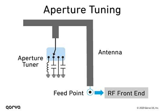
Aperture Tuning Diagram
 

RON and COFF Explained

Aperture tuning primarily uses tuner switches and tunable capacitors. The main figures of merit for these switches are ON state resistance (RON) and OFF state capacitance (COFF), as shown below. For tunable capacitors, it is critical to have a wide range for tuning capacitance and a good Q factor (Quality factor). RON and COFF significantly affect antenna efficiency. RON's impact is greatest when the voltage is low; the impact of COFF is greatest when the voltage is high. Strategic placement of switches with low RON or low COFF optimizes tuning for different frequencies.
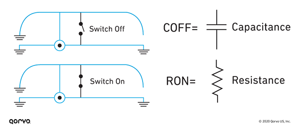
RON and COFF Diagram
 

In the OFF state, the COFF of an aperture tuner contributes to the capacitive loading on the antenna, lowering the resonant frequency. The higher the COFF of the tuner, the more the frequency shifts away from the antenna’s natural resonance.

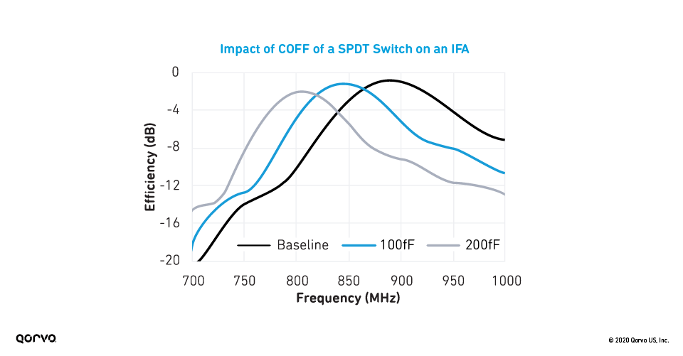
Figure below demonstrates the impact of the COFF of a Single Pole Double Throw (SPDT) switch on the simulated efficiency of an Inverted F Antenna (IFA). The baseline measurement shown was taken without the SPDT placed at the tuning location. Once added, the COFF of each port was set to 100 fF and 200 fF.

 Peak Efficiency (dB)Resonant Freq. (MHz)
 Baseline  -0.86  890 
 COFF = 100 fF  -1.16  850 
 COFF = 200 fF  -2.01  810 


Graph of the Impact of COFF of a SPDT Switch on an IFA
Figure 1.

COFF Antenna Tuning

When moving from the baseline antenna to the low COFF switch, a frequency shift of 40 MHz and a 0.3 dB drop in peak efficiency is observed. An additional 40 MHz shift and 0.85 dB drop in peak efficiency occur when moving from the low 100fF COFF to the high 200fF COFF switch. The result is an 80 MHz frequency shift and a total efficiency drop of 1.15 dB from baseline.
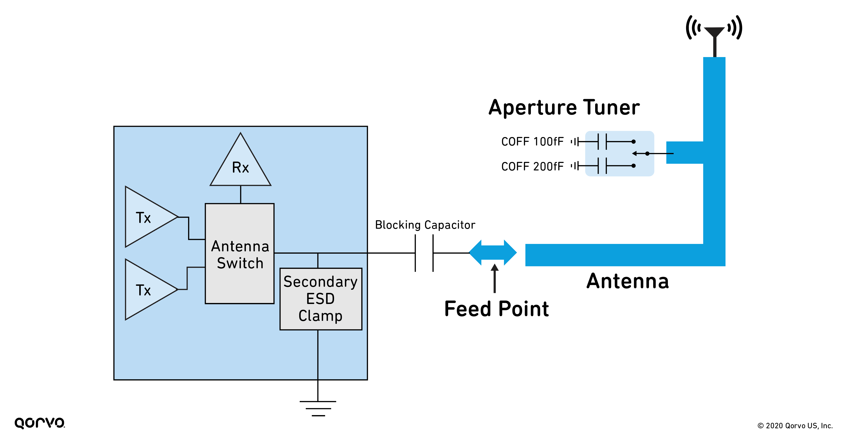
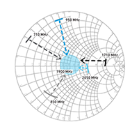
Diagram of a Re-tuned Antenna
Figure 2.
 

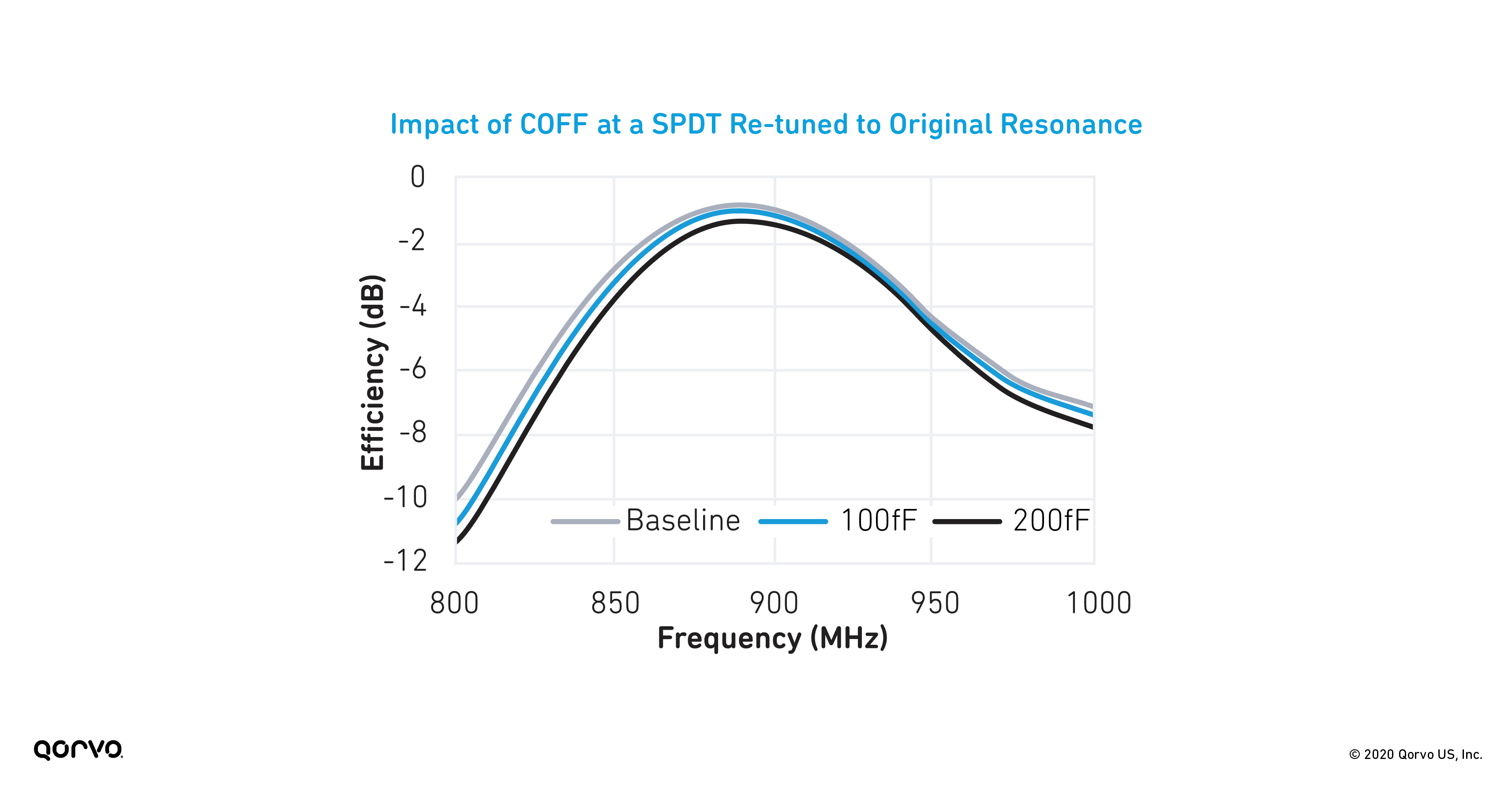
To offset the frequency shift caused by the tuner’s COFF, one port of the SPDT can be used to switch in an inductor to re-tune the antenna back to its natural resonant frequency. In this scenario, the antenna is tuned twice – once by the tuner’s COFF and a second time by the inductor used to re-align the antenna to its original resonance. However, this method comes at the expense of efficiency and bandwidth, as evidenced by Figure 3, which shows the antenna’s efficiency when re-tuned to its original 890 MHz resonance.

 Peak Efficiency (dB)Resonant Freq. (MHz)
 Baseline  -0.86  890 
 COFF = 100 fF  -0.98  890 
 COFF = 200 fF  -1.33  890 


Graph of the Impact of COFF at a SPDT Re-tuned to Original Resonance
Figure 3.


While it was possible to account for the COFF of the SPDT, the high COFF switch resulted in a 0.47 dB decrease in peak efficiency compared to the baseline measurement. To facilitate the mobile phone’s frequency band swapping on an antenna, aperture tuning is necessary.

Our mobile devices are obviously getting more complicated and sophisticated. This is putting a strain on the antenna and its ability to meet all the needs of the user. Unfortunately, not just any antenna tuning component can meet the needs of these sophisticated device systems. As outlined in this blog, using insufficient high COFF tuners results in significant frequency shifts that de-tune the antenna and reduce overall antenna efficiency. Thus, low COFF switches are best when trying to balance
between antenna efficiency and frequency band requirement needs.

Stay up to date with us.

Sign up for notification on new products, product/process change notifications (PCNs) and end of life (EOL) alerts.

Sign Up

Qorvo products are at work connecting, protecting and powering the planet. We bring core radio frequency (RF) and power technologies and solutions to automotive, consumer, defense & aerospace, industrial & enterprise, infrastructure and mobile markets.

Stay Connected

  • Facebook
  • X
  • LinkedIn
  • YouTube
  • Products
  • Solutions
  • Design Hub
  • New Products
  • Product Compliance
  • Blog Posts
  • Events & Trade Shows
  • News Releases
  • Success Stories
  • Technical Articles
  • About Us
  • Careers
  • Corporate Videos
  • Quality
  • Locations
  • Investors
  • How to Buy
  • Forums
  • Portals
  • Contact Us
  • Subscription Center
Site MapFeedbackLegalPrivacySupply Chain Transparency

© 2026 Qorvo US, Inc

|

+1-833-641-3810

Mobile 5G Device Antenna Tuning Demystified

September 2, 2020

S-Parameters Graph

5G is bringing a significant increase in new bands that mobile antennas must support. More than ever before, there’s a need for handset designers to use more aperture tuners on a single antenna due to the complexity of the new phone designs. While each addition of an aperture tuner helps optimize the overall antenna performance for each band, it sometimes comes at the cost of antenna efficiency. Without the proper balance of antenna efficiency and performance of each band on an antenna, the overall device performance and range will suffer.

Each antenna has a frequency at which it resonates naturally – it is at this frequency that we see maximum antenna efficiency. Aperture tuning is accomplished by placing a shunt capacitor (to lower the resonant frequency) or shunt inductor (to raise the resonant frequency) on the antenna. Multiple capacitors and inductors help tune an antenna to multiple frequencies by using an antenna tuner switch – as displayed in the below image.

Aperture Tuning Diagram
 

RON and COFF Explained

Aperture tuning primarily uses tuner switches and tunable capacitors. The main figures of merit for these switches are ON state resistance (RON) and OFF state capacitance (COFF), as shown below. For tunable capacitors, it is critical to have a wide range for tuning capacitance and a good Q factor (Quality factor). RON and COFF significantly affect antenna efficiency. RON's impact is greatest when the voltage is low; the impact of COFF is greatest when the voltage is high. Strategic placement of switches with low RON or low COFF optimizes tuning for different frequencies.

RON and COFF Diagram
 

In the OFF state, the COFF of an aperture tuner contributes to the capacitive loading on the antenna, lowering the resonant frequency. The higher the COFF of the tuner, the more the frequency shifts away from the antenna’s natural resonance.

Figure below demonstrates the impact of the COFF of a Single Pole Double Throw (SPDT) switch on the simulated efficiency of an Inverted F Antenna (IFA). The baseline measurement shown was taken without the SPDT placed at the tuning location. Once added, the COFF of each port was set to 100 fF and 200 fF.

 Peak Efficiency (dB)Resonant Freq. (MHz)
 Baseline  -0.86  890 
 COFF = 100 fF  -1.16  850 
 COFF = 200 fF  -2.01  810 


Graph of the Impact of COFF of a SPDT Switch on an IFA
Figure 1.

COFF Antenna Tuning

When moving from the baseline antenna to the low COFF switch, a frequency shift of 40 MHz and a 0.3 dB drop in peak efficiency is observed. An additional 40 MHz shift and 0.85 dB drop in peak efficiency occur when moving from the low 100fF COFF to the high 200fF COFF switch. The result is an 80 MHz frequency shift and a total efficiency drop of 1.15 dB from baseline.

Diagram of a Re-tuned Antenna
Figure 2.
 

To offset the frequency shift caused by the tuner’s COFF, one port of the SPDT can be used to switch in an inductor to re-tune the antenna back to its natural resonant frequency. In this scenario, the antenna is tuned twice – once by the tuner’s COFF and a second time by the inductor used to re-align the antenna to its original resonance. However, this method comes at the expense of efficiency and bandwidth, as evidenced by Figure 3, which shows the antenna’s efficiency when re-tuned to its original 890 MHz resonance.

 Peak Efficiency (dB)Resonant Freq. (MHz)
 Baseline  -0.86  890 
 COFF = 100 fF  -0.98  890 
 COFF = 200 fF  -1.33  890 


Graph of the Impact of COFF at a SPDT Re-tuned to Original Resonance
Figure 3.


While it was possible to account for the COFF of the SPDT, the high COFF switch resulted in a 0.47 dB decrease in peak efficiency compared to the baseline measurement. To facilitate the mobile phone’s frequency band swapping on an antenna, aperture tuning is necessary.

Our mobile devices are obviously getting more complicated and sophisticated. This is putting a strain on the antenna and its ability to meet all the needs of the user. Unfortunately, not just any antenna tuning component can meet the needs of these sophisticated device systems. As outlined in this blog, using insufficient high COFF tuners results in significant frequency shifts that de-tune the antenna and reduce overall antenna efficiency. Thus, low COFF switches are best when trying to balance
between antenna efficiency and frequency band requirement needs.

Stay up to date with us.

Sign up for notification on new products, product/process change notifications (PCNs) and end of life (EOL) alerts.

Sign Up

Qorvo products are at work connecting, protecting and powering the planet. We bring core radio frequency (RF) and power technologies and solutions to automotive, consumer, defense & aerospace, industrial & enterprise, infrastructure and mobile markets.

Stay Connected

  • Facebook
  • X
  • LinkedIn
  • YouTube
  • Products
  • Solutions
  • Design Hub
  • New Products
  • Product Compliance
  • Blog Posts
  • Events & Trade Shows
  • News Releases
  • Success Stories
  • Technical Articles
  • About Us
  • Careers
  • Corporate Videos
  • Quality
  • Locations
  • Investors
  • How to Buy
  • Forums
  • Portals
  • Contact Us
  • Subscription Center
Site MapFeedbackLegalPrivacySupply Chain Transparency

© 2026 Qorvo US, Inc

|

+1-833-641-3810

Qorvo
  • Products
  • Solutions
  • Design Hub
  • Support
  • About Us
Qorvo
Qorvo
Qorvo
  • Products
  • Solutions
  • Design Hub
  • Support
  • About Us
Qorvo
Qorvo