Unlocking Full Duplex DOCSIS® 3.1 Architecture with DPD and 75-Ohm CATV Switches
 Consumers and the pressure from 5G wireless are pushing cable TV (CATV) providers to step up their game more than in the past. The CATV industry is now on the fast track to setting new standards for the next-gen cable ecosystem, including Full Duplex (FDX) DOCSIS 3.1, which promises to deliver 10 Gbps data rates upstream and downstream on existing hybrid fiber-coaxial (HFC) systems.
But achieving FDX will require highly linear devices enabled for digital predistortion (DPD) — including 75-ohm CATV switches. This blog explores how DPD works in CATV optical nodes, as well as some considerations for selecting the right switch for your application.
FDX requires more Pout, fewer errors, and DPD
A distributed access architecture (DAA), along with fiber deep and remote PHY/remote MAC PHY, are moving some of the functions out of the head end and to optical nodes closer to the subscriber. However, it’s impossible to achieve 10 Gbps upstream and downstream — and remain competitive with 5G cellular infrastructure — on a DAA without designing for DOCSIS 3.1 FDX architecture.
We covered some of the RF challenges to implementing Full Duplex DOCSIS in a previous blog. Two of the most critical elements for enabling FDX include the following:
- Modulation error ratio (MER). MER is one of the measurements of error and linearity in the CATV system. The challenge with FDX is to have fewer errors (lower MER) while getting a lot of RF power. To do this, you need DPD.
- Digital predistortion (DPD). DPD is a software-based method for removing distortion using digital signal processing techniques. It allows a power amplifier (PA) to have the same MER and output power but at a lower current, which are all essential for hitting the higher power output requirements for FDX. This technique is widely used in the wireless market, but it hasn’t been as common in CATV networks.
Related Blog Post: Enabling 10 Gbps Cable Networks with Full Duplex DOCSIS 3.1
In short, the PA will need to be highly efficient, hit 76.8 dBmV composite output power and have better ACPR (linearity) to ultimately meet the MER specifications for FDX. Although the PA hardware provides most of the linearity improvement, DPD makes a smaller but essential contribution.
How digital predistortion works in CATV nodes
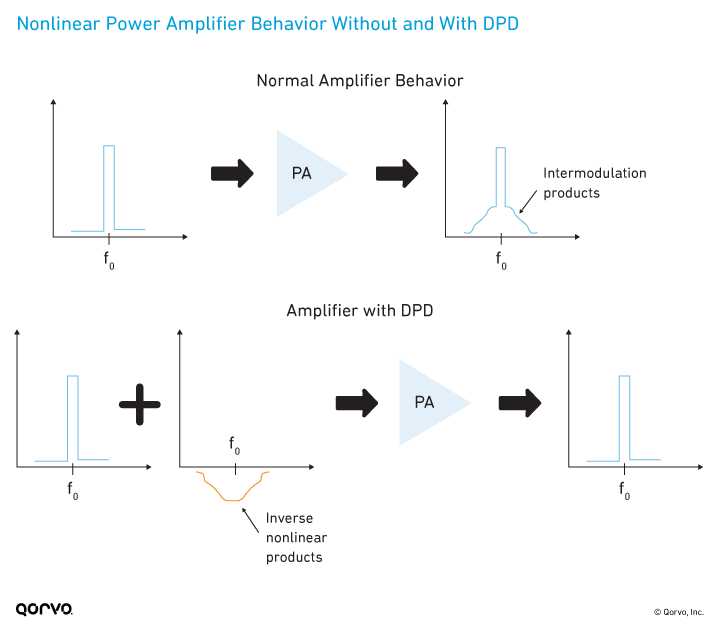
At a high level, DPD models and predicts the nonlinear behavior of an amplifier and injects inverse signals at the input of the PA, thereby reducing the nonlinear behavior in the amplifier and overall current consumption. The following figure shows nonlinear characteristics of a PA without and with DPD.
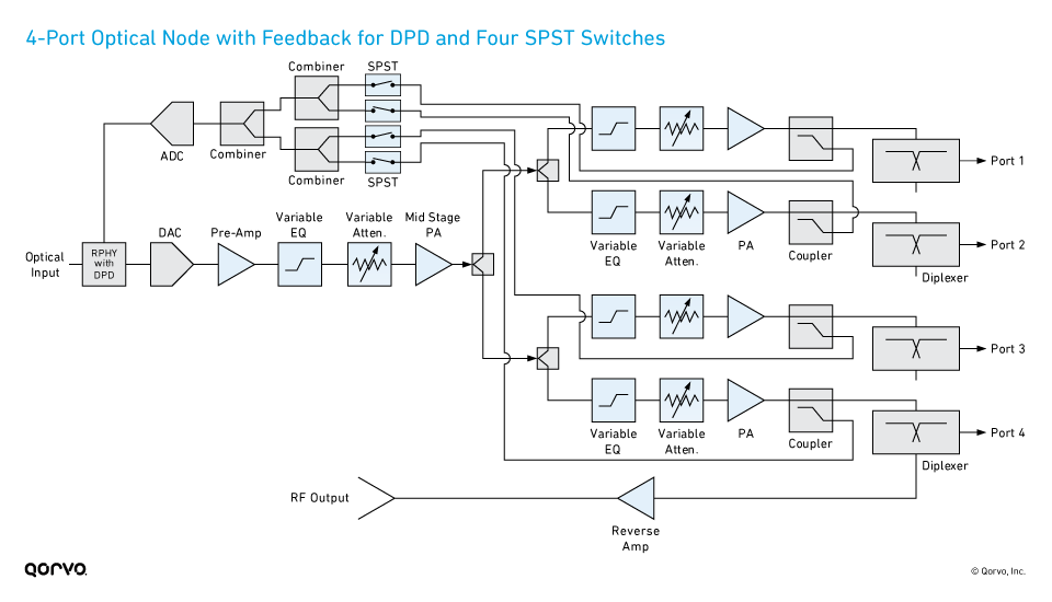
For a CATV optical node, the digital-to-analog converter (DAC) circuit in the node uses software to measure each of the PA outputs through the coupler to determine which PA has the worst linearity. The circuit then calculates a DPD algorithm based on the worst measurement and sends the correction downstream to all the PAs. The worst device is corrected the most, and the end result is multiple devices that run better than without the DPD algorithm.
In a typical 4-port optical node, the RF amplifiers in the chain consume 85 watts, of which 72 watts is from the last power doubler PA. Using DPD linearizes each PA and reduces overall power consumption as much as 20%.
SP4T, SPDT or SPST solution for DPD
Enabling DPD in a cable optical node requires 75‑ohm switches. When should you choose an SPST, SPDT or SP4T switch? It’s all about the geometry — the physical layout — of the node. A node in the field could have outputs on either side of the box, and it may not be able to have traces going into a single SP4T switch.
There’s no single right way to design for DPD. Ultimately, the design approach is based on the individual customer application, layout and preference, as well as performance requirements and cost.
Glossary of Terms
- ACPR: adjacent channel power ratio
- ADC: analog-to-digital converter
- CATV: cable TV
- DAA: distributed access architecture
- DAC: digital-to-analog converter
- DOCSIS: Data Over Cable Service Interface Specification
- DPD: digital predistortion
- FDX: full duplex
- HFC: hybrid fiber-coaxial
- MER: modulation error ratio
- PA: power amplifier
- PHY: physical layer
- SP4T: single pole, four throw
- SPDT or SP2T: single pole, double throw
- SPST: single pole, single throw
The following block diagrams show three different design approaches to implement DPD in a 4-port optical node:
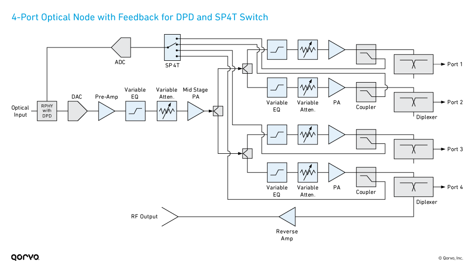
- One DPD pathway + one SP4T switch. In a standard 4-port optical node, the circuit has one DAC driving four outputs to monitor four PAs. It uses one SP4T switch, one analog-to-digital converter (ADC) and the DPD algorithm to adjust all four PAs.
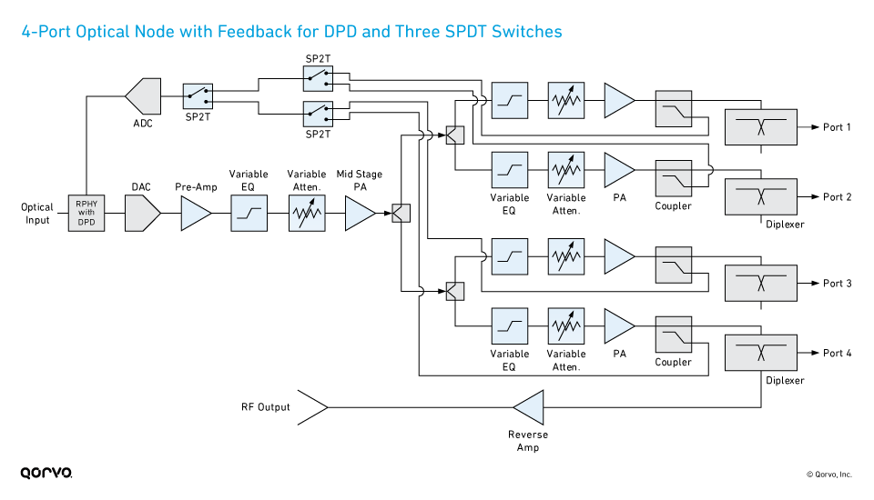
- One DPD pathway + 3-4 switches. This approach uses an ADC and three SPDT switches or four SPST switches, rather than one ADC and one SP4T switch. All four output amplifiers can be monitored individually to determine the best DPD correction factor. This approach uses more components and switches, but it could give more precise output or might work better with the individual node design. The first schematic below uses three SPDT switches, while the second diagram uses four SPST switches.
Absorptive and reflective switches
In addition to the number of switches and throws, it’s important to choose the correct type of switch for these DPD node applications. Your choices are an absorptive switch or a reflective switch. Here are some of the key differences:
Absorptive switch:
- Is terminated internally to 75 ohms when the switch is “off”
- Higher isolation
- Higher insertion loss (due to the extra internal switching)
- Dissipates less power (due to the terminations)
- Higher cost
Reflective switch:
- Is not terminated internally and is open when the switch is “off”
- Lower isolation
- Better insertion loss
- Higher power handling
- Faster switching time
- Lower cost
The choice comes down to cost versus performance. If power handling and lower insertion loss are key to the design, pick a reflective switch. If higher isolation is important and the design can handle the extra insertion loss and higher costs, select an absorptive switch.
The takeaway
Implementing DPD will require more design resources, as well as higher costs for additional components and switches. However, the advantages outweigh these downsides because you get adaptive coefficients; self-calibrating, higher-linearity PA outputs; lower current consumption — and above all, FDX.
Qorvo’s 75-ohm switch portfolio for DPD
To learn more about our 75-ohm switches to enable DPD in optical nodes, view the following products or our Cable TV application information for interactive block diagrams: