5 Things to Consider When Designing Fixed Wireless Access (FWA) Systems

April 13, 2018

fixed-wireless-access-rollup_320x180.pngOne of the earliest uses of 5G will be fixed wireless access (FWA), which promises to deliver gigabit internet speeds. FWA can be delivered to homes, apartments and businesses in a fraction of the time and cost of traditional cable/fiber installations. As with any technological advance, FWA brings new design hurdles and technology decisions. Let’s dig into five things to consider when designing FWA systems:

  • The choice of frequency spectrum: millimeter wave (mmWave) or sub-6 GHz
  • Achieving higher data rates with antenna arrays
  • All-digital or hybrid beamforming
  • Power amplifier (PA) technology choices: silicon germanium (SiGe) or gallium nitride (GaN)
  • Choosing components from today’s RF front-end (RFFE) product portfolios


#1: Spectrum choice: mmWave or sub-6 GHz

The first decision is whether to use mmWave or sub-6 GHz frequencies for FWA:

  • mmWave. These higher frequencies offer a large amount of contiguous spectrum available at low cost. mmWave supports component carriers up to 400 MHz wide and enables gigabit data rates. The challenge is path loss due to obstacles like vegetation, buildings and interference. However, don’t assume FWA is useful only in clear line-of-sight settings between the base station and the home — FWA can actually perform very well in both urban and suburban settings. It’s true that vegetation and interference are challenging, but these can be overcome with antenna arrays that provide high gain.
  • Sub-6 GHz. This lower-frequency spectrum helps overcome the problems caused by obstructions, but at a cost. Only 100 MHz of contiguous spectrum is available, so data rates are lower.

 
Efficient use of frequency range (sub-6 GHz or mmWave) is critical to scaling deployments. The choice for any situation will depend on balancing the goals of speed and coverage.
 

#2: Achieving higher data rates with antenna arrays

An FWA system will also need to employ active antenna systems (AAS) and massive MIMO (multiple input/multiple output) to deliver gigabit service.

  • AAS provides many directional antenna beams. These beams are redirected in less than a microsecond, enabling beamforming that offsets the greater path loss associated with high frequencies.
  • Massive MIMO uses arrays of dozens, hundreds or even thousands of antennas, allowing simultaneous transmission of single or many data streams to each user. The results are improved capacity, reliability, high data rates and low latency. Beamforming also enables less inter-cell interference and better signal coverage.

Learn more about AAS and massive MIMO: How Carrier Networks Will Enable 5G
 

#3: All-digital or hybrid beamforming

A third element to consider is the type of beamforming to employ — all-digital or hybrid.

All-digital approach

The most obvious choice in mmWave base station applications is to upgrade the current platform. You could explore extending all-digital beamforming massive MIMO platforms used for sub-6 GHz frequencies, but this isn’t a plug-and-play solution.

An all-digital approach faces these design constraints:

  • Power consumption. Digital beamforming uses many low-resolution analog-to-digital converters (ADC). But ADCs with a high sampling frequency and a standard number of effective bits of resolution can consume a large amount of power. This power consumption can become the bottleneck of the receiver. A large AAS with massive bandwidth presents a huge challenge for an all-digital beamforming solution. Essentially, the power consumption will limit the design.
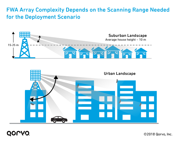
  • The need for two-dimensional scanning in dense urban environments. The required scanning range depends on the deployment scenario, as shown in the figure below. In a dense urban landscape, wide scan ranges are needed in both azimuth (~120°) and elevation (~90°). For suburban deployments, a fixed or limited scan range (< 20°) in the elevation plane may be enough. A suburban deployment requires limited scan range or half as many active channels to achieve the same effective isotropic radiated power (EIRP), which reduces power and cost.
Remember: An array’s size is dependent on:

  • The scanning range (azimuth and elevation)
  • Desired EIRP

EIRP is the product of:

  • The number of active channels
  • Conducted transmit power of each channel
  • Beamforming gain (array factor)
  • Intrinsic antenna element gain

fig1-fwa-array-complexity-fnl.png

To achieve the target EIRP of 75 dBm and beamforming gain, an all-digital solution using today’s technology would need 16 transceivers. This would equal a total power consumption of 440 W. But for outdoor passive-cooled, tower-top electronics, it’s challenging to thermally manage more than 300 W from the RF subsystem. We need new technological solutions.

Efficient GaN Doherty PAs with digital predistortion (DPD) may provide the required margin, but these devices are still in development for mmWave applications. But it won’t be long before we see an all-digital beamforming solution. Several developments will make it a reality:

  • Next-generation digital-to-analog and analog-to-digital converters that save power
  • Advances in mmWave CMOS transceivers
  • Increased levels of small-signal integration


fig5-fwa-tradeoffs-antenna-array-rffe-technology.png


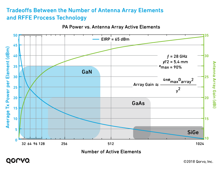
As you can see from the table below, a SiGe PA can achieve 65 dBm EIRP using 1024 active channels. However, by using GaN technology for the front end, the same EIRP can be achieved with 16x fewer channels.
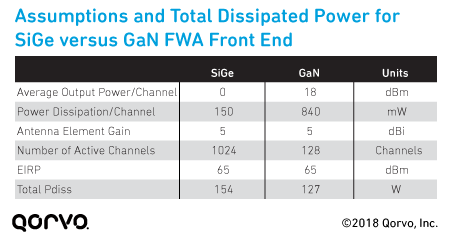
fig6-sige-vs-gan-fwa-front-end-assumptions.png

A GaN FWA front end provides other benefits:

  • Lower total power dissipation. To ensure an accurate comparison, the GaN power dissipation includes an extra 19.2 watts, to account for the 128 beamformer branches needed to feed the front ends. As shown in the following figure, at the target EIRP of 65 dBm, GaN provides a lower total power dissipation (127 Pdiss) than SiGe. This is better for tower-mounted system designs.
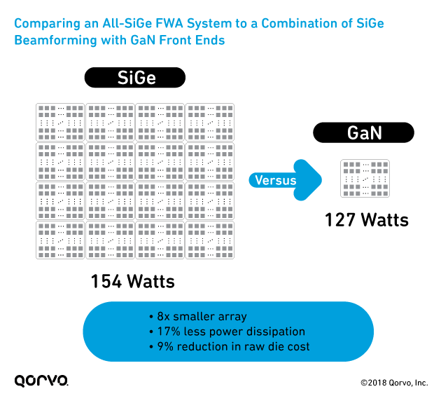
fig7-comparison-sige-gan-beamforming.png

  • Better reliability. GaN is more reliable than SiGe, with >107 hours MTTF at 200°C junction temperature. SiGe’s junction temperature limit is around 130°C.
  • Reduced size and complexity. GaN’s high power capabilities reduces array elements and size, which simplifies assembly and reduces overall system size.

 
The takeaway: In wireless infrastructure applications, reliability is imperative because equipment must last for at least 10 years. For FWA, GaN is a better choice than SiGe for reliability, cost, lower power dissipation and array size.
 

#5: Choosing from today’s RF technology

The last consideration is selecting product solutions that are being used in real-world applications. Several RF companies are positioned to support the development of sub-6 GHz and cmWave/mmWave FWA infrastructure. Qorvo, for instance, is already supplying products for many Tier 1 and Tier 2 supplier field trials. Across the RF industry, examples of products for FWA include:

  • Sub-6 GHz products: Dual-channel switch/LNA modules and integrated Doherty PA modules
  • cmWave/mmWave: Integrated transmit and receive modules

 
Additionally, in the 5G infrastructure space, several things are a must:

  • Integration
  • Meeting passive cooling requirements at high temperatures

 
To support these trends, Qorvo has created integrated transmit and receive modules for cmWave/mmWave, as well as integrated GaN FEMs. These integrated modules include a PA, switch and LNA, and have high gain to drive the core beamformer RFICs. To meet the infrastructure passive-cooling specification, we use GaN-on-SiC to support the higher junction temperature.

For more information on Qorvo solutions for FWA, click on the images below, where you'll find product details and interactive block diagrams.

Qorvo Block Diagram: mmWave Massive MIMO GaN Front Ends

Learn more about these products:

  • TGP2100, QPC1000
  • TGA2594-HM
  • QPF4005
  • QPF4006

FWA is approaching — fast

FWA implementation has begun, and full commercialization is approaching rapidly. Today, we believe hybrid beamforming is the best approach. Additionally, GaN, along with SiGe core beamforming, meets FCC EIRP targets of 75 dBm / 100 MHz base station targets. This approach also minimizes cost, complexity, size and power dissipation.

For technical guidance and applications support, please visit our Technical Support information.
 

Stay up to date with us.

Sign up for notification on new products, product/process change notifications (PCNs) and end of life (EOL) alerts.

Sign Up

Qorvo products are at work connecting, protecting and powering the planet. We bring core radio frequency (RF) and power technologies and solutions to automotive, consumer, defense & aerospace, industrial & enterprise, infrastructure and mobile markets.

Stay Connected

  • Facebook
  • X
  • LinkedIn
  • YouTube
  • Products
  • Solutions
  • Design Hub
  • New Products
  • Product Compliance
  • Blog Posts
  • Events & Trade Shows
  • News Releases
  • Success Stories
  • Technical Articles
  • About Us
  • Careers
  • Corporate Videos
  • Quality
  • Locations
  • Investors
  • How to Buy
  • Forums
  • Portals
  • Contact Us
  • Subscription Center
Site MapFeedbackLegalPrivacySupply Chain Transparency

© 2026 Qorvo US, Inc

|

+1-833-641-3810

5 Things to Consider When Designing Fixed Wireless Access (FWA) Systems

April 13, 2018

fixed-wireless-access-rollup_320x180.pngOne of the earliest uses of 5G will be fixed wireless access (FWA), which promises to deliver gigabit internet speeds. FWA can be delivered to homes, apartments and businesses in a fraction of the time and cost of traditional cable/fiber installations. As with any technological advance, FWA brings new design hurdles and technology decisions. Let’s dig into five things to consider when designing FWA systems:

  • The choice of frequency spectrum: millimeter wave (mmWave) or sub-6 GHz
  • Achieving higher data rates with antenna arrays
  • All-digital or hybrid beamforming
  • Power amplifier (PA) technology choices: silicon germanium (SiGe) or gallium nitride (GaN)
  • Choosing components from today’s RF front-end (RFFE) product portfolios


#1: Spectrum choice: mmWave or sub-6 GHz

The first decision is whether to use mmWave or sub-6 GHz frequencies for FWA:

  • mmWave. These higher frequencies offer a large amount of contiguous spectrum available at low cost. mmWave supports component carriers up to 400 MHz wide and enables gigabit data rates. The challenge is path loss due to obstacles like vegetation, buildings and interference. However, don’t assume FWA is useful only in clear line-of-sight settings between the base station and the home — FWA can actually perform very well in both urban and suburban settings. It’s true that vegetation and interference are challenging, but these can be overcome with antenna arrays that provide high gain.
  • Sub-6 GHz. This lower-frequency spectrum helps overcome the problems caused by obstructions, but at a cost. Only 100 MHz of contiguous spectrum is available, so data rates are lower.

 
Efficient use of frequency range (sub-6 GHz or mmWave) is critical to scaling deployments. The choice for any situation will depend on balancing the goals of speed and coverage.
 

#2: Achieving higher data rates with antenna arrays

An FWA system will also need to employ active antenna systems (AAS) and massive MIMO (multiple input/multiple output) to deliver gigabit service.

  • AAS provides many directional antenna beams. These beams are redirected in less than a microsecond, enabling beamforming that offsets the greater path loss associated with high frequencies.
  • Massive MIMO uses arrays of dozens, hundreds or even thousands of antennas, allowing simultaneous transmission of single or many data streams to each user. The results are improved capacity, reliability, high data rates and low latency. Beamforming also enables less inter-cell interference and better signal coverage.

Learn more about AAS and massive MIMO: How Carrier Networks Will Enable 5G
 

#3: All-digital or hybrid beamforming

A third element to consider is the type of beamforming to employ — all-digital or hybrid.

All-digital approach

The most obvious choice in mmWave base station applications is to upgrade the current platform. You could explore extending all-digital beamforming massive MIMO platforms used for sub-6 GHz frequencies, but this isn’t a plug-and-play solution.

An all-digital approach faces these design constraints:

  • Power consumption. Digital beamforming uses many low-resolution analog-to-digital converters (ADC). But ADCs with a high sampling frequency and a standard number of effective bits of resolution can consume a large amount of power. This power consumption can become the bottleneck of the receiver. A large AAS with massive bandwidth presents a huge challenge for an all-digital beamforming solution. Essentially, the power consumption will limit the design.
  • The need for two-dimensional scanning in dense urban environments. The required scanning range depends on the deployment scenario, as shown in the figure below. In a dense urban landscape, wide scan ranges are needed in both azimuth (~120°) and elevation (~90°). For suburban deployments, a fixed or limited scan range (< 20°) in the elevation plane may be enough. A suburban deployment requires limited scan range or half as many active channels to achieve the same effective isotropic radiated power (EIRP), which reduces power and cost.

Remember: An array’s size is dependent on:

  • The scanning range (azimuth and elevation)
  • Desired EIRP

EIRP is the product of:

  • The number of active channels
  • Conducted transmit power of each channel
  • Beamforming gain (array factor)
  • Intrinsic antenna element gain

fig1-fwa-array-complexity-fnl.png

To achieve the target EIRP of 75 dBm and beamforming gain, an all-digital solution using today’s technology would need 16 transceivers. This would equal a total power consumption of 440 W. But for outdoor passive-cooled, tower-top electronics, it’s challenging to thermally manage more than 300 W from the RF subsystem. We need new technological solutions.

Efficient GaN Doherty PAs with digital predistortion (DPD) may provide the required margin, but these devices are still in development for mmWave applications. But it won’t be long before we see an all-digital beamforming solution. Several developments will make it a reality:

  • Next-generation digital-to-analog and analog-to-digital converters that save power
  • Advances in mmWave CMOS transceivers
  • Increased levels of small-signal integration


fig5-fwa-tradeoffs-antenna-array-rffe-technology.png


As you can see from the table below, a SiGe PA can achieve 65 dBm EIRP using 1024 active channels. However, by using GaN technology for the front end, the same EIRP can be achieved with 16x fewer channels.

fig6-sige-vs-gan-fwa-front-end-assumptions.png

A GaN FWA front end provides other benefits:

  • Lower total power dissipation. To ensure an accurate comparison, the GaN power dissipation includes an extra 19.2 watts, to account for the 128 beamformer branches needed to feed the front ends. As shown in the following figure, at the target EIRP of 65 dBm, GaN provides a lower total power dissipation (127 Pdiss) than SiGe. This is better for tower-mounted system designs.

fig7-comparison-sige-gan-beamforming.png

  • Better reliability. GaN is more reliable than SiGe, with >107 hours MTTF at 200°C junction temperature. SiGe’s junction temperature limit is around 130°C.
  • Reduced size and complexity. GaN’s high power capabilities reduces array elements and size, which simplifies assembly and reduces overall system size.

 
The takeaway: In wireless infrastructure applications, reliability is imperative because equipment must last for at least 10 years. For FWA, GaN is a better choice than SiGe for reliability, cost, lower power dissipation and array size.
 

#5: Choosing from today’s RF technology

The last consideration is selecting product solutions that are being used in real-world applications. Several RF companies are positioned to support the development of sub-6 GHz and cmWave/mmWave FWA infrastructure. Qorvo, for instance, is already supplying products for many Tier 1 and Tier 2 supplier field trials. Across the RF industry, examples of products for FWA include:

  • Sub-6 GHz products: Dual-channel switch/LNA modules and integrated Doherty PA modules
  • cmWave/mmWave: Integrated transmit and receive modules

 
Additionally, in the 5G infrastructure space, several things are a must:

  • Integration
  • Meeting passive cooling requirements at high temperatures

 
To support these trends, Qorvo has created integrated transmit and receive modules for cmWave/mmWave, as well as integrated GaN FEMs. These integrated modules include a PA, switch and LNA, and have high gain to drive the core beamformer RFICs. To meet the infrastructure passive-cooling specification, we use GaN-on-SiC to support the higher junction temperature.

For more information on Qorvo solutions for FWA, click on the images below, where you'll find product details and interactive block diagrams.

Qorvo Block Diagram: mmWave Massive MIMO GaN Front Ends

Learn more about these products:

  • TGP2100, QPC1000
  • TGA2594-HM
  • QPF4005
  • QPF4006

FWA is approaching — fast

FWA implementation has begun, and full commercialization is approaching rapidly. Today, we believe hybrid beamforming is the best approach. Additionally, GaN, along with SiGe core beamforming, meets FCC EIRP targets of 75 dBm / 100 MHz base station targets. This approach also minimizes cost, complexity, size and power dissipation.

For technical guidance and applications support, please visit our Technical Support information.
 

Stay up to date with us.

Sign up for notification on new products, product/process change notifications (PCNs) and end of life (EOL) alerts.

Sign Up

Qorvo products are at work connecting, protecting and powering the planet. We bring core radio frequency (RF) and power technologies and solutions to automotive, consumer, defense & aerospace, industrial & enterprise, infrastructure and mobile markets.

Stay Connected

  • Facebook
  • X
  • LinkedIn
  • YouTube
  • Products
  • Solutions
  • Design Hub
  • New Products
  • Product Compliance
  • Blog Posts
  • Events & Trade Shows
  • News Releases
  • Success Stories
  • Technical Articles
  • About Us
  • Careers
  • Corporate Videos
  • Quality
  • Locations
  • Investors
  • How to Buy
  • Forums
  • Portals
  • Contact Us
  • Subscription Center
Site MapFeedbackLegalPrivacySupply Chain Transparency

© 2026 Qorvo US, Inc

|

+1-833-641-3810

Qorvo
  • Products
  • Solutions
  • Design Hub
  • Support
  • About Us
Qorvo
Qorvo
Qorvo
  • Products
  • Solutions
  • Design Hub
  • Support
  • About Us
Qorvo
Qorvo