An Op-Ed on Op-Amp Modeling
February 22, 2024
Op-Amp circuits are simply fascinating. The elegant application of feedback with op-amps was a major attraction to pursuing electronics for me. Simulation, through the straightforward ability to visualize circuit behavior, is an ideal way to peruse feedback ideas and cultivate one's op-amp circuit intuition.
Simulating op-amp circuits brings up a painful irony: While it's hard for the IC designer not to use SPICE to design the op-amp, it's also hard to use SPICE to simulate the final op-amp in some larger application circuit, or at least it's much harder than I would like. The point of this blog installment is to fix this problem, i.e., solve op-amp modeling once and for all.
Here's the issue. SPICE excels at transistor-level simulation. However, the IC designer does everything possible to make it hard to tell if there are any transistors in the op-amp. Nobly, they want you to be able to use op-amp cookbooks for your designs and see no deviation from ideal op-amp behavior due to transistor limitations. The irony completes when you realize there aren't any native circuit elements in SPICE that behave like an op-amp. It's difficult to make a model of an op-amp that isn't either potentially more difficult to solve than the original transistor-level implementation or simply too simplified to be of value. That's the technical issue. And there's no reason an IC manufacturer would know how to model an op-amp at the application level—it simply isn't part of the design process of an op-amp. This puts the manufacturer in an uncomfortable situation. Their customers demand models that are useful for designing circuits, but the manufacturer typically doesn’t have the requisite modeling expertise. Further complicating the situation are the competing interests at play. The manufacturer is interested in showcasing their op-amps, highlighting beneficial matters of product differentiation—lower offsets and higher Power Supply Rejection Ratio (PSRR). This showcasing agenda is pursued without regard for a design flow that leads to the best possible design.
As the op-amp manufacturer lacks modeling expertise, they collaborate with modeling consultant contractors who have a distinct focus. The contractor wants to be able to reuse one of their proprietary template circuits and merely adjust it to fit the dominant pole, phase margin, output voltage range and a few other things. The template uses a ‘contraptous’ method implemented with only the simplest and most common SPICE primitives. Such models serve the interest of the consultant since he doesn't have to make different models for their different IC manufacturing clients. Such models also stand up to committee review as they only use features that are available in all SPICE programs. Except the model templates are typically authored in a context absent of a detailed understanding of how SPICE solvers work so the resultant model may need to be tweaked from one simulator to another anyway. And, of course, a technical solution founded on the lowest common denominator of existing base technologies usually isn’t ideal.
The result of these competing approaches is complicated op-amp models that are incorrect and difficult to solve in larger circuits. First, the incorrectness. For example, take offset voltage. The manufacturer wants the model to show that the offset voltage and bias currents are lower than some other company's op-amp. They want the model to illustrate some representative offset. But the IC designer, being a responsible adult, nulled out offsets as best as possible. Across production, some units will have a positive offset and some a negative. Unless there's an error in the design of the product, there is no systematic offset. But, due to the manufacturers’ approach the models are required to show a systematic offset voltage in the interest of highlighting product differentiation. The problem with a model that is solely intended to highlight a matter of product differentiation is that if you optimize a design that requires the op-amp to regulate something, the optimized point will be incorrect but centered around the offset voltage of the model, doubling the worst-case error. You could have skipped simulation, used op-amp cookbook design methodology, used a cheaper op-amp and had a better circuit. This problem extends to other aspects of op-amp modeling. For example, PSRR. The IC designer nulled it out as best as possible. Sometimes, the magnitude might be known (at least as well as one can tell from a log scale), but not the phase. I've never seen a datasheet that showed PSRR as the complex number it is. The mistake of having offsets and PSRR not centered on the true average value is particularly a problem for circuits with multiple op-amps. I can't imagine the luxury of having multiple op-amps with identical offsets and PSRRs.
On a deeper level, the reason these approaches have led unchecked to such a state of op-amp modeling is that the models typically aren't supported by people familiar with appropriate design flow via simulation. The IC manufacturers' application engineers lament that customers don't observe things like input common-mode range and require it to be "modeled." But, as a matter of design flow, people would usually be better off if they simulate without input common-mode range modeled and then audit if it were ever exceeded during the operation of the circuit. It's an analogous situation to breakdown voltage. Unless a device is avalanche grade (i.e., intended to safely break down in deployment), it is better not to include breakdown in the simulation but let the voltage go as it will and have the simulated device withstand everything. Then, after the simulation completes, audit the results to see if any voltage rating was ever exceeded. Otherwise, it's hard to know if breakdown occurred. The design flow might even produce a design that doesn't work until after some device smoked.
That paragraph contains a controversy. IC manufacturers' application engineers can be contemptuous of their customers' ability to design. It's only human to come to that since a person who's responsible for supporting only a few ICs naturally becomes quick to judge someone who isn't as familiar with those few. Somehow, the point gets lost that IC manufacturers' application engineers don't buy reels of parts that go into products that have to survive in the open market like their customers do. For that reason, as certain as any final analysis, I don't think of customers as dumber than myself. Besides, otherwise, I'd eventually run out of people dumber than me. Every simulator I've ever written has always been to make people feel smart by enabling them with tools that cultivate their understanding of the circuits they design.
All that said, I will come to the point. QSPICE includes a new native circuit element in the interest of simplifying op-amp modeling. It is a transconductance that sources current from the rails (instead of magically operating as its own power supply), and as the output approaches a rail, it switches over to a resistance like a square law FET does. It acts like a well-designed complementary grounded source output stage of a Rail-to-Rail Output (RRO) op-amp.
The usual topology of an internally compensated RRO op-amp includes a Miller-multiplied capacitance from this output to an internal node. That topology is also a native circuit element in QSPICE. This simulation shows how to extract the open loop response of the QSPICE RRO op-amp native circuit element:
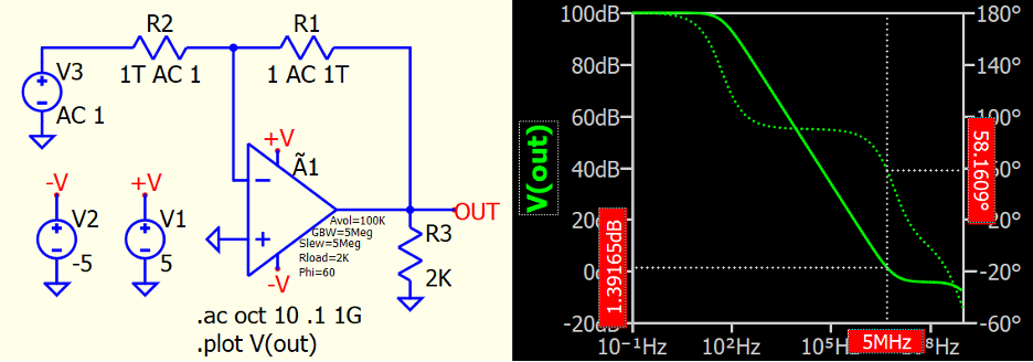
R1's value is "1 AC 1T." That means it's a 1 Ω resistor for the DC solution but a 1e12 Ω resistor for the AC analysis. Conversely, R2 is 1e12 Ω for the DC solution but 1 Ω for the AC analysis. The ability to use a different value for AC and DC is from HSPICE¹ and is used to solve for the bias point as a voltage follower but then do the AC analysis directly in open loop. Instance parameters Avol, GBW, Slew, and Phi are the Open Loop Voltage Gain, Gain Bandwidth, Slew Rate, and Phase Margin, respectively. Because an RRO has a high impedance output, the voltage gain is essentially infinite. That's why the parameter Rload is necessary to specify the load resistance used to measure the open loop voltage gain.
Simple-minded equations are used to set up the RRO Op-Amp device. In the waveform window, the cursor is set to 5MHz, but the gain is 1.4dB instead of zero and the phase shift is 58° instead of 60°. Adjust the instance GBW and Phi to match the op-amp of interest.
The RRO device supports everything necessary to model a complete op-amp: dominant pole, phase margin, stochastic noise, input capacitance both normal and common mode), voltage and current output capability, etc. Below is the full list of instance parameters:
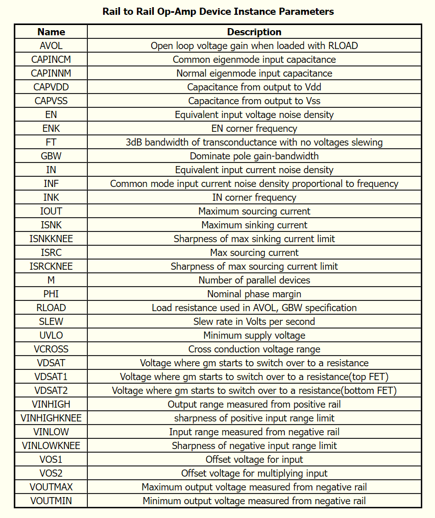
And, yes, you can give it an offset voltage directly as an instance parameter to determine the impact of device precision and scatter.
Let me clarify the input capacitances, CAPINCM and CAPINNM. CAPINCM is the capacitance seen when both inputs are driven together, and CAPINNM is the capacitance seen when driven differentially. This is not the capacitance between the inputs but the capacitance that is of interest in stability analysis of the normal mode. Some IC manufacturers mistakenly list the pin-to-pin capacitance on the datasheet as the normal-mode capacitance.
The QSPICE RRO Op-Amp device solves several issues. Besides making everyone an expert op-amp modeling person by just filling in the values, it is completely transparent about what is and is not modeled. You get to understand what the model is doing.
Some people will find it important that the QSPICE RRO Op-Amp device computes blindingly fast. The time it takes to solve a circuit depends more on the number of equations to solve than the number of devices. You can determine how many equations it takes to solve a circuit by adding ".options acct" to your SPICE simulation. So, to count the number of internal nodes in an op-amp model, place an instance of the model on an otherwise empty schematic and ground all the pins. Run any simulation and check the output on the console. It should read "Circuit Equations: 2," meaning the QSPICE RRO Op-Amp device has two internal nodes. The same test on a generic op-amp model from industry is usually in the range of 40 to 150 equations. This isn't important if you are only simulating a few op-amps, but it becomes important when you present the rest of the system as a test vector to your op-amp circuit.
The QSPICE RRO Op-Amp device also enables you to investigate your circuits' behavior over temperature in a way that normal vendor-supplied op-amp models do not. You can adjust the GBW in the interest of considering the effect of temperature on your op-amp circuit. When you have a simple resistive feedback network, the phase shifts before the magnitude, which causes data acquisition errors.
The example shows how to add a temperature dependence to the GBW:
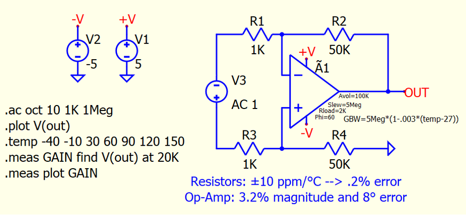
I’ve simply written the value of the GBW as an expression that includes its tempco.
In signal conditioning, the temperature dependence of op-amp GBW can cause an error that easily exceeds the error due to the temperature dependence of the passive components. For example, it's straightforward to specify 25ppm/°C resistors, but let's say we go with 10ppm/°C. That yields a .2% error from -40°C to 150°C. In this simulation, we see a 3.2% error in magnitude and 8° error in phase for a hypothetical analysis frequency of 20kHz, as might be used in prospecting for oil. This is a plot of gain over temperature considering only the effect of the op-amp’s GBW temperature dependence:
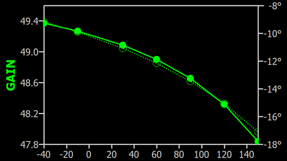
The QSPICE RRO Op-Amp device will allow you to design a data acquisition system and predict its performance downhole or on the surface, no matter if it's in the Arctic or Sudan.
¹HSPICE is a Synopsis Registered Trademark
