BAW vs. SAW RF Filters
June 22, 2023
This post first appeared on the Mouser Electronics website, by Jean-Jacques (JJ) DeLisle, a frequent contributor to Mouser Electronics’ blog.
Why Are RF Filters Needed?
Radio frequency (RF) filters are cornerstone components in all RF/microwave systems, especially wireless communication systems with many channels or bands. The primary function of an RF filter is to attenuate signals in certain undesired frequency bands while only minimally impacting signals in desired frequency bands.
RF filters are crucial, as there are many instances where undesirable signals (known as interference) can result in degradation or even damage to system functionality. In wireless communication systems, various RF filters are used at the input of receivers to attenuate signals outside the band of interest. RF filters are also used to reduce harmonics, spurious content, and out-of-band leakage from transmitter circuits. In many cases with modern electronics such as smartphones, these devices are equipped with several wireless communication technologies that could interfere with each other if not properly isolated using RF filters—a design challenge known as coexistence (Figure 1).
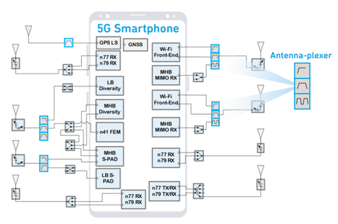
Figure 1: An example 5G smartphone diagram featuring a variety of wireless communication hardware with callouts to the various filter types needed.
What Applications Require an RF Filter?
As the compact design of most modern communication technologies limits physical isolation, engineers use RF filters to enhance that isolation and ensure that these products meet the necessary standards. These can be standards set by national and international regulatory agencies, such as the U.S. Federal Communications Commission (FCC) and the global Electronic Communications Committee (ECC), as well as wireless standards such as Wi-Fi, 4G/5G, Bluetooth®, and Zigbee. Many modern electronics also use accessory services that require their own filtering, such as the global positioning system (GPS) and other geolocation technologies, as well as near-field communication (NFC) technology.
Given the extremely compact nature of modern wireless communication systems, there is a need for highly compact filters that still exhibit a high Q factor and can readily be integrated into filter banks for multi-band filtering applications. In many cases, distinct RF filters are needed for every frequency band to minimize crosstalk and mitigate nonlinear products. To meet this need, engineers often use acoustic wave filters (AWFs).
In essence, AWFs are constructed of electroacoustic transducers on piezoelectric substrates that can convert electrical energy into acoustic/mechanical energy and vice versa. In this way, AWFs allow for the conversion of high-frequency signals into acoustic wave signals that can then be conditioned by acoustic resonators and filtering technology before being converted back into high-frequency signals. The advantage over other electromagnetic filter technologies is that acoustic wave phenomena are roughly five orders of magnitude smaller than electromagnetic filtering phenomena. Practically, these factors result in acoustic filters that can be as much as an order of magnitude smaller than traditional electromagnetic filter types for similar performance.

The two main types of AWFs—bulk acoustic wave (BAW) and surface acoustic wave (SAW) filters—convert electrical and acoustic signals using interdigital transducers. BAW filters direct the signal energy through the bulk of the substrate, while SAW filters direct the signal energy along the surface of the substrate. Though this distinction may seem simple at first, the reality is that these different approaches result in significant differences in performance and frequency capabilities.
SAW filters are generally less complex to design and fabricate, as the fabrication process mainly consists of developing surface structures. Conversely, BAW filters require precise control of substrate thickness and layered structures, such as acoustic reflectors precisely spaced in a stack.
However, the relative dimensions and physics associated with BAW filters allow them to be designed for even higher frequency operation and higher Q performance than is typically possible with SAW technology; this is due to the physical limitations of electroacoustic transduction at the surface. Moreover, BAW filters can be fabricated on technology compatible with standard IC processing systems and typically demonstrate higher power handling capability. BAW filters also exhibit lower frequency drift with temperature than SAW filters, though there are SAW filter technologies that incorporate temperature compensation design features or are otherwise fabricated in such a way as to minimize temperature sensitivity.
In general, SAW filters can be practically fabricated to operate to 2000MHz or 2500MHz. In comparison, it is possible to manufacture BAW filters to 10GHz or even beyond. SAW and BAW technologies directly compete in the frequency ranges between 100MHz and roughly 2500MHz.
When Would an Engineer Use BAW vs. SAW?
When selecting a filter for a given application, it is essential to understand the requirements of the filtering application and interpret the filter's electrical specifications. Every filter application will have a center frequency, bandwidth, desired signal level, and rejection requirement. A system engineer typically lays out these system requirements. The engineer selects the filter to ensure that the filter meets these requirements while maintaining the budget and develops a plan for incorporating the filter within the system design. In the case of modern wireless equipment, this usually involves designing filter banks composed of many filters that meet stringent requirements to conform to wireless and regulatory agency standards.
The following are the key electrical specifications for designing RF filters:
- Filter type (low-pass, high-pass, bandpass, notch/pass-reject)
- Pass band frequency (Hz)
- Rejection frequency (Hz)
- Rejection or out-of-band rejection (dB)
- Attenuation (dB)
- Insertion loss (dB)
- Isolation (dB)
- Selectivity (dB)
- Q factor
- Ripple (dB)
- Input power handling (dB)
- Input and output impedance matching (Ohms)
Most wireless communication standards emphasize bandpass filters used in tandem with several other bandpass filters to enable multi-band filtering. This is a widespread application for both SAW and BAW filters, as their compact size allows for relatively small filter banks compared to other filter technology. These bandpass filters operate to reduce the out-of-band signal content as seen by the receiver. This is an important function, as out-of-band frequency content can result in a desensitized receiver with a lower signal-to-noise ratio (SNR) or higher bit error rate (BER). Moreover, filters are often used at the output of a transmitter to reduce the number of nonlinear products, such as harmonics and spurs, created by the relatively higher-power transmitter devices. This use of filter aids enhances the adjacent channel leakage ratio (ACLR) and adjacent channel power ratio (ACPR). Additionally, through this use of filters, wireless transmitters that would otherwise fail a wireless standards test may pass the test without substantial redesign.
There are also cases where a wireless communication system has been designed and deployed but faces challenges in the field that went undetected during early evaluation. In this case, it may be possible to upgrade the radio with enhanced filters to mitigate these issues if they can be addressed through more rigorous filtering. For example, if a radio experiences interference near a critical operating frequency band, a filter with a higher Q and better out-of-band rejection would allow for better operation than the extant filter.
In general, SAW filters are less expensive than BAW filters, and an extensive selection of SAW filters is available on the market. SAW filters aren't generally offered beyond 2500MHz operating frequencies. However, if the design requires the highest degree of performance or higher frequency operation (for example, in the higher frequencies of 3G, 4G, Wi-Fi 6E, and sub-6GHz 5G), then BAW filters are a better choice (Figure 2). BAW filters are often designed to achieve higher frequency operation and better passband attenuation, out-of-band rejection, power handling, and Q factor than SAW filters.

Are There Specific Filters for Specific Applications?
SAW and BAW filters must be precisely designed to achieve the desired operation. For a given application, it is possible to have custom SAW and BAW filters designed and fabricated in significant volumes. Fortunately, BAW and SAW filter manufacturers tend to design and produce large volumes of SAW and BAW filters that meet the needs of various markets and applications, such as Wi-Fi and 4G LTE/5G. Specific SAW and BAW filters are also made to combat coexistence challenges for prominent wireless standards, such as Wi-Fi and Bluetooth® low energy (LE)Bluetooth Low Energy.
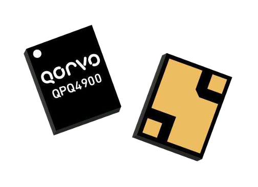
An example of a widely available acoustic filter is the Qorvo QPQ4900 BAW filter for the 5G NR TDD band n79 (Figure 3). This sub-band bandpass BAW filter is designed for macrocells and small cells that may have potential interference from nearby Wi-Fi 6E wireless networks. Another example is the Qorvo QPQ1063 GPS SAW diplexer, designed for use in the L1/L2 GPS bands.
Conclusion
RF filters are crucial components in modern wireless communication systems. They attenuate undesired frequency bands to minimize interference and ensure proper system functionality. Due to the physical limitations of technology, RF filters are not always ideal and may result in some loss of passband frequencies. Acoustic wave filters, specifically BAW and SAW filters, are popular choices due to their small size and high Q factor. SAW filters are less complex to design and fabricate, while BAW filters offer higher frequency operation and higher Q performance. Engineers must consider the requirements of their filtering application and the electrical specifications of the filter—such as filter type, pass band, stop band, and insertion loss—to select the appropriate filter for their system design.
