Easy Methods to Optimize Mobile Antenna Tuning
May 25, 2023
Creating mobile devices with multiple antennas involves a challenging balancing act. If you consider all the elements a mobile device designer has to contend with, it’s a lot. For starters, mobile devices have separate antennas for cellular (low, mid, high), Wi-Fi, Bluetooth®, Ultra-Wideband and diversity bands. They also have to contend with smaller, sleeker devices that have more capabilities, in addition to RF single range.
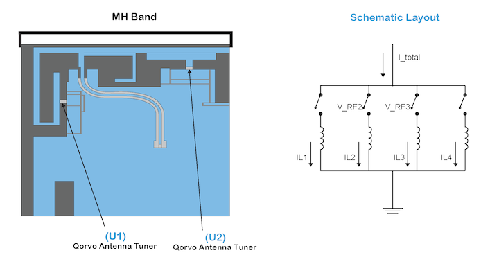
Figure 1: Mid and high Wi-Fi band Qorvo antenna tuner
Using Qorvo antenna tuners helps optimize the antenna performance for each of these bands. But adding tuners does come at the cost of antenna efficiency. So, design care must be taken to maintain proper antenna efficiency and performance. Doing so requires optimizing the PC board layout. Qorvo offers a wide selection of antenna tuning components that provide best-in-class performance for a wide array of applications. The Qorvo antenna tuners were strategically placed to take advantage of their excellent RF performance characteristics to tune over the spectrum of mid and high bands and offer high efficiency.
As shown below in Figure 2, two PC boards with antennas and antenna tuning components take up a combined area of 195mm2. Our goal is to reduce this area by 35%, while meeting peak RF performance. We’ll explain how to achieve this goal using tradeoffs between efficiency and performance.
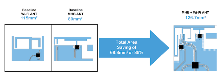
Figure 2: Baseline mid-to-high band and Wi-Fi antennas versus goal reduction.
The mid-to-high band (MHB) antenna on its own is a difficult design challenge. Adding Wi-Fi 2.4 GHz and 5 GHz antennas makes things much harder to design and reduces form-factor. It comes down to using the best components to optimize the antenna PC board area itself.
In Figure 3 below, we can see the PC board layout design of the MHB and Wi-Fi antennas. This layout design is optimized for a size reduction of 35% and for a best-in-class RF signal range. Let’s break down how mobile device designers will achieve 35% size reduction and superior smartphone RF range.
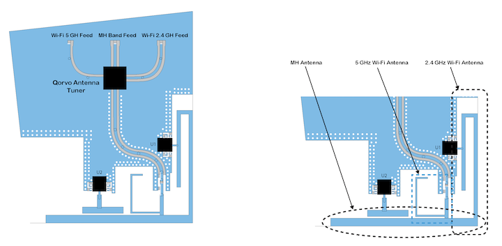
Figure 3: Mid-to-high band and Wi-Fi mobile antenna solution.
Each tuning state covers four different cellular bands, as shown in Table 1 below. The antenna we are designing has 3 RF branches covering four cellular frequency bands (MHB) and Wi-Fi bands of 2.4 GHz and 5 GHz for each tuning state.
An important thing to note, the design shown in Figure 3 has both the MHB and Wi-Fi bands in mind. Each of these bands, 1, 3, 40 and 7, as well as the Wi-Fi bands, operate simultaneously. Also, the individual antennas meet peak performance at each cellular and Wi-Fi switch state, as shown in the table below.

Table 1: MH band and Wi-Fi tuned to work simultaneously.
Let’s take a closer look at the MHB and the 2.4 GHz sections. As shown in Figure 4, the Qorvo antenna tuner is used for the MH and 2.4 GHz Wi-Fi tuners. The combined tuner and board layout optimizes the cellular and Wi-Fi 2.4 GHz bands.
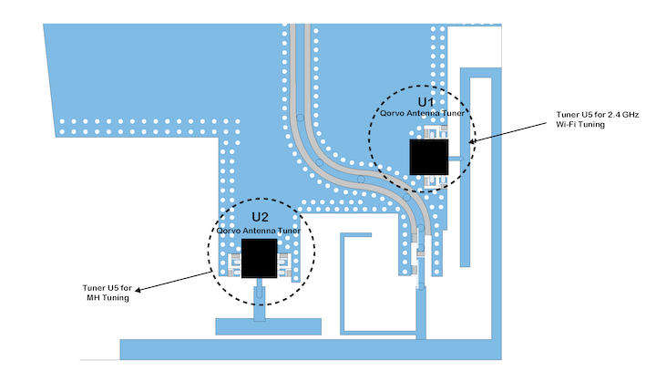
Figure 4: MHB and 2.4 GHz antenna tuners and design.
U1 connects to this area to compensate for any change which is caused by the U2 tuner. Keeping the resonance for the Wi-Fi 2.4 GHz band constant. In fact, these two sections of the antenna are interdependent. They operate together to generate one tunable resonance and two constant resonances. This all occurs while keeping the efficiency of both bands at peak performance.
The third section of this antenna structure uses a metal connection to operate – outlined in the blue dotted line box. This is a monopole antenna covering the Wi-Fi 5GHz band, as shown in Figure 5. This PC board layout covers the large bandwidth of the Wi-Fi 5 GHz band (5150 to 5850 MHz).
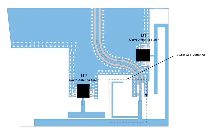
Figure 5: 5 GHz Wi-Fi monopole antenna structure
To reduce the size of the antenna area in the smartphone, we use a Qorvo antennaplexer chipset. This reduces cost and size. See Figure 6 below. This antennaplexer combines three different RF signals from the feeds of each antenna. This approach also reduces the RF radiating area in the smartphone, mitigating interferences. Moreover, it combines three independent radiators into one small PC board area.
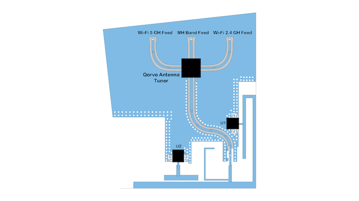
Figure 6: MH, Wi-Fi 2.4 & 5 GHz antennas with antennaplexer.
The major benefits of using the antennaplexer are:
- PCB size reduction
- High radiation efficiency in all the required bands
So, do these size reductions and performance enhancements improve peak performance? Yes – see Figure 7. The size reductions using Qorvo antenna tuners and antennaplexer increases efficiency.
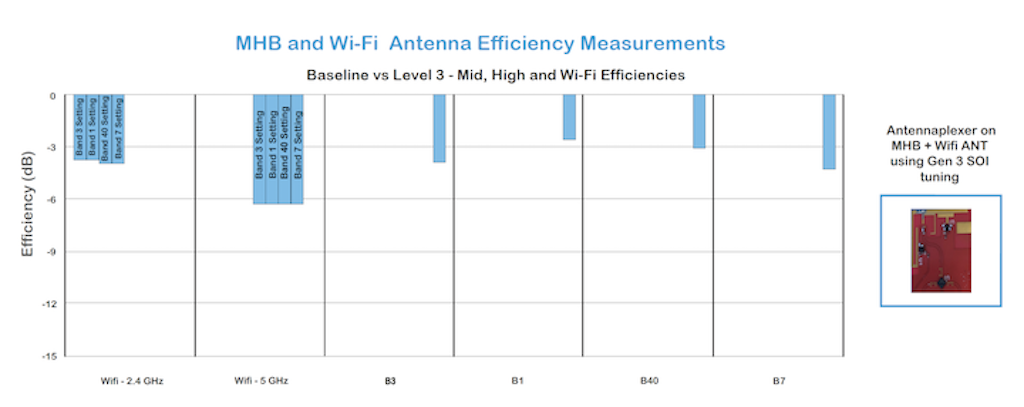
Figure 7: MHB and Wi-Fi efficiency measurement results.
Smartphones or other mobile devices are becoming more complicated to design. This is due to smaller, sleeker devices with more capability. Engineers sometimes struggle to meet these requirements while optimizing performance. They also need to design fast to meet company time-to-market requirements. Qorvo is here to assist. We are here for technical help and with new and improved next-generation products. Using our antenna tuners and antennaplexers, along with our PC board design guidance, Qorvo can help you achieve a design that meets your customer needs. For more detailed information on this described application, please feel free to contact us at technical support.
