How Qorvo is Optimizing the X-Band Phased Array Radar System
April 7, 2026
Modern X-band radar systems rely heavily on Active Electronically Scanned Array (AESA) architectures to achieve rapid beam steering, high spatial resolution and multi-target tracking capability. In these systems, integrating beamformer ICs (BFICs) with advanced RF front-end modules (RFFEMs) enables exceptional control over phase, amplitude and power distribution across thousands of transmit/receive (T/R) channels. However, this level of integration introduces challenges in power delivery, thermal management and precise bias sequencing—particularly when using high-efficiency Gallium Nitride (GaN) technology. Addressing these challenges is essential to realizing the full performance potential of AESA radars, ensuring fast response times, improved detection range and robust operation in complex radar environments.
An Overview of Phased Array Radar System
Two-dimensional planar phased arrays are commonly used in AESA radar systems. In these designs, the circuitry and antenna elements are integrated on opposite sides of the same PC board. This approach offers significant economies of scale and compactness, but it also introduces challenges in layout, power management and thermal performance.
A large AESA may contain thousands of RF components such as T/R front-end modules (FEM) and Beamformer IC (BFIC). The FEMs include power amplifiers (PAs) and low-noise amplifiers (LNAs) and switches that require precise, synchronized and stable DC bias voltages. As operating frequencies rise and element spacing decreases, these T/R modules must become smaller. The resulting tight lattice makes RF routing, bias circuitry, power lines and control logic increasingly complex.
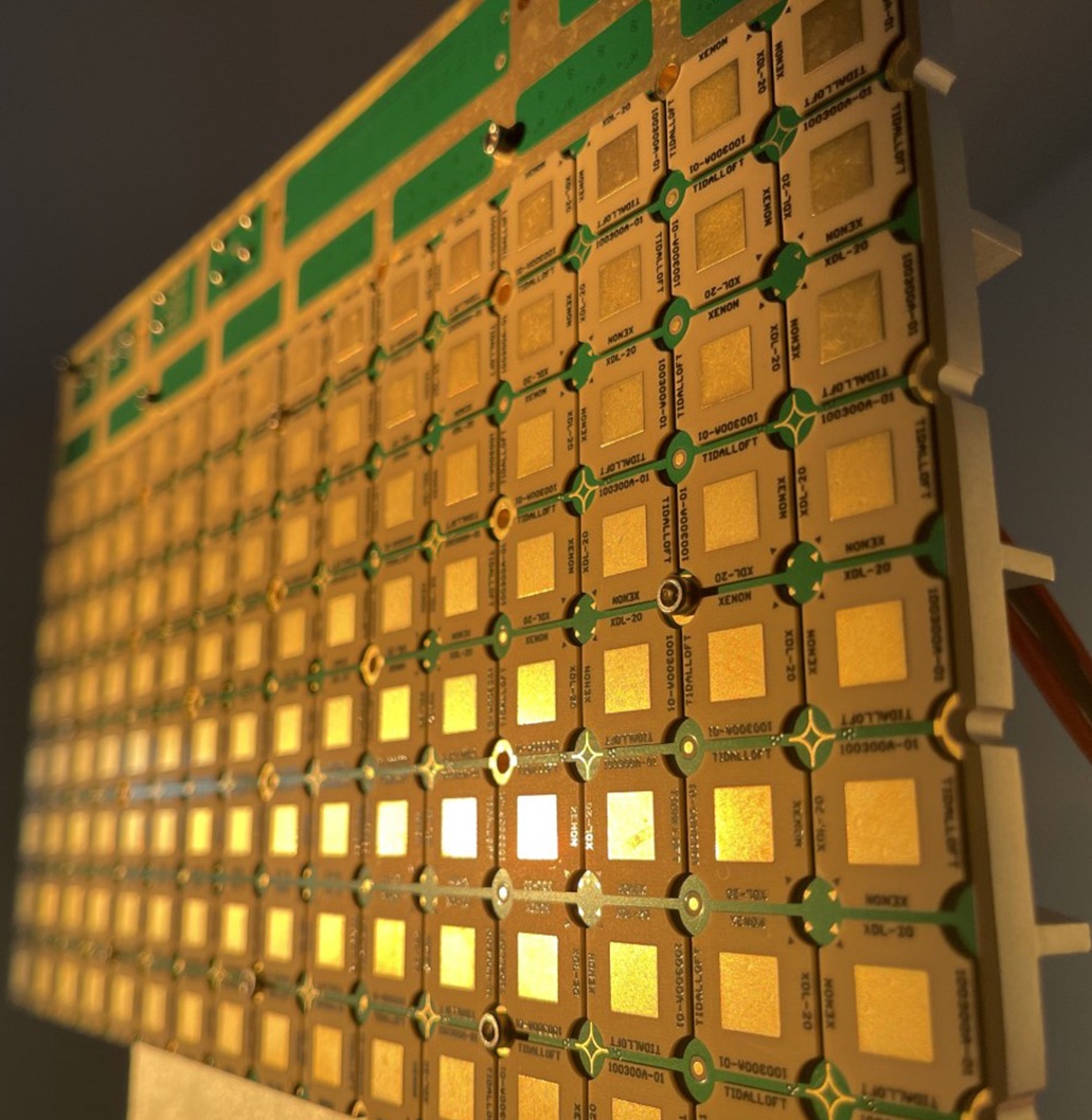
Figure 1: X-band AESA radar system using Qorvo beamforming integrated circuits.
The ability to distinguish small drones from clutter or other airborne objects has become increasingly critical as global security demands evolve. The advantages of AESA phased array technology extend beyond agility and reliability. With their ability to perform multiple functions simultaneously—such as air-to-air and air-to-ground monitoring, AESA radar systems provide unmatched flexibility and mission-critical performance. Their planar, low-profile architecture enables integration into modern aircraft and unmanned platforms where Size, Weight and Power with Cost (SWaP-C) efficiencies are vital. The absence of moving parts greatly improves system reliability, while “soft failure” capability ensures continued performance even if individual T/R channels fail. This combination of speed, multi-functionality and resilience gives AESA radar systems a decisive edge for modern defense operations, particularly in addressing emerging threats such as unmanned aerial vehicles (UAVs).
A System Level Review
AESA radar systems represent a major leap forward in radar technology, particularly in X-band applications where high frequency and precision are paramount. Unlike mechanically steered antennas that rely on physical movement to direct their beams, AESA antennas can electronically steer their signals within microseconds. This electronic beamsteering offers far greater agility, speed and reliability. Allowing radar systems to track multiple fast-moving targets simultaneously without mechanical wear or delay.
Operating at X-band frequencies, AESA radars strike an ideal balance between resolution, range and antenna size. This makes them well-suited for defense, surveillance and airborne applications where accuracy, compactness and environmental resilience are critical. These systems deliver high-resolution imaging, long-range detection and robust performance in adverse weather conditions, ensuring consistent situational awareness in even the most challenging environments.
A key factor in X-band radar performance is precise phase control of each antenna element in the phased array. Accurate phase and amplitude adjustment enable fast, reliable beam steering for tracking multiple targets at once. Qorvo’s beamformer ICs deliver this precision with independent phase shift and attenuation control, improving radar performance in complex, dynamic environments.
To achieve the full potential of AESA radar, engineers increasingly integrate the latest front-end module and BFIC technologies. (See Figure 2 below). Advanced GaN and Gallium Arsenide (GaAs) front-end semiconductor materials provide the high-power density, efficiency and low noise performance needed for precise beam control and long-range detection. While silicon-based BFICs offer digital intelligence to manage fast, fine-grained phase and amplitude adjustments. Together, these technologies deliver optimized performance—enhancing sensitivity, reducing false detections and minimizing DC power consumption. The result is a new generation of compact, energy-efficient X-band radar systems that achieve superior SWaP-C performance.

Figure 2: Typical block diagram of RF front-end with beamformer and digital backend.

Figure 3: Typical X-Band Radar Tile Array with 64 antenna elements
By combining AESA architectures with advanced GaN, GaAs and BFIC front-end integration, developers can create radar systems capable of tracking and classifying drones with pinpoint accuracy. This integration also sets new standards for agility, reliability and efficiency in next-generation defense and aerospace applications. In the block diagram below, the RFFE modules use GaN technology on both the PA and switches, helping achieve performance beyond legacy systems.

Figure 4: System block diagram of Qorvo’s BFIC and RF front-end modules.
Additionally, radar systems using GaN technology for their PAs and switches offer higher output-power and efficiency but also introduce unique biasing challenges. Unlike GaAs devices, which are positively biased, GaN requires a negative Gate bias voltage for operation.
This negative Gate biasing adds another layer of complexity. GaN is a depletion-mode field-effect transistor (FET), meaning it requires a negative Gate voltage during operation. This negative Gate voltage—often referred to as the “pinch-off” voltage—must be applied before the positive Drain voltage is turned on. If this bias sequence is not carefully controlled, the GaN device can be damaged. Fortunately, we have reference design guidance in an application note (please contact the Qorvo application team for more information) to simplify this process, making reliable FEM bias sequencing in radar systems much easier to implement.
Enhancing the RF Performance
Using the test boards and setup shown in Figure 4, along with the components described in the block diagram above, we demonstrate the performance enhancements achieved by combining the GaN/GaAs RFFEM with the silicon-based BFIC. As we will show, the combination of these technologies in the AESA system yields significant performance benefits.

Figure 5: Test system setup
On its own, the silicon-based BFIC provides limited transmit and receive power, with a receive coherent Gain of about 9 dB. When paired with the RFFEM, an additional 15 dB of Gain is achieved, resulting in a total receive coherent Gain of approximately 24 dB. Furthermore, integrating the RFFEM considerably reduces the BFIC-only RF coherent Noise Figure from around 15 dB to an average of 2.5 dB—representing a substantial improvement in system performance. See Figure 6.

Figure 6: Coherent Noise Figure across the operating band.
On the transmit side, the RF front-end (RFFE) delivers a saturated output power (Psat) of 32.5 dBm with a Gain at Psat of 44 dB, significantly higher than the BFIC’s standalone transmit output of 13 dBm (PO1dB). Once again, we see that combining the RFFE with the BFIC provides a substantial improvement in transmit power performance.

Figure 7: Operating Gain at Psat +44 dBm.
In modern radar systems, optimizing the AESA begins with tightly integrating the key RF components. Variable phase and amplitude control is now consolidated within BFICs, each containing multiple phase and amplitude blocks for fine-beam steering. Similarly, the PA, LNA and T/R switch can be integrated into compact T/R modules that interface directly with the BFIC. This high level of integration improves performance, simplifies layout and enhances system reliability.
In a phased array system, Root-Mean-Square (RMS) phase error is a measure of how much the actual phase of each element in a phased array deviates, on average, from an ideal reference signal. Likewise, RMS amplitude error describes the average deviation of each element’s amplitude from its ideal value. Both are crucial metrics for X-Band radar system performance, as they quantify the accuracy of the individual phase shifters and attenuators used in each array element. High RMS phased or amplitude errors can lead to a degraded beam shape and reduced antenna performance.
As shown in Figure 8, the phase and amplitude RMS values remain low, indicating strong system performance. Amplitude error is the difference between a signal’s ideal amplitude and its measured value. It can arise from distortion or non-ideal behavior in components such as antennas, amplifiers or mixers. These imperfections, often caused by non-linearities or impedance mismatches, can alter signal amplitude and reduce signal accuracy. Because of this, amplitude error is an important metric for evaluating and calibrating RF systems to ensure reliable performance.
Phase error represents the deviation between the actual and ideal phase of a signal and can be introduced by oscillator mismatch, environmental noise or imperfections in measurement equipment. In digital communication and radar systems, excessive phase error degrades performance, reduces measurement accuracy and can distort radar impulse responses. The impact depends on whether the error varies linearly or exhibits behavior such as distortion. Understanding and minimizing phase error is therefore essential for maintaining precise beamforming, accurate target detection, and overall system fidelity.


Figure 9: Transmit and receiver RMS Phase and Amplitude Error.
Monostatic phased array radars, which use the same aperture for transmitting and receiving with a phased array antenna, require precise timing coordination. Critical parameters include transmit pulse duration, pulse repetition time (PRT), and duty cycle. Because these systems operate in half-duplex mode, fast and accurate T/R switching is essential, particularly in search radars detecting close-range targets. Fast switching of the PA and LNA is essential to minimize signal latency, improve radar response time, and extend detection range. As shown in Figure 9 below, the switching speed is well below the average required threshold of 150 nanoseconds, helping to achieve minimal signal latency and improved radar response time.


Figure 9: Receive to transmit and transmit to receive switching time.
Conclusion
Integrating RF front-end modules with beamformer ICs provides measurable performance improvements across X-band AESA radar systems. This combination enhances the receive coherent Gain to 32.5 dB, reduces noise figures to 2.5 dB, and increases transmit power output to 32.5 dBm. Beyond these quantitative gains, tighter integration simplifies design complexity, reduces latency through faster T/R switching and improves overall system efficiency and reliability. As radar technology advances, the synergy between BFIC and RFFEM integration will continue to define the next generation of compact, high-performance AESA radar systems optimized for modern defense and aerospace applications.

Table 1: Performance Summary
Additionally, you can find more information on this subject by visiting our Qorvo Design Hub for a rich assortment of videos, technical articles, white papers, tools and more. For technical support, please visit Qorvo.com or reach out to Technical Support.
About the Authors
Our authors bring a wealth of technical expertise in developing and optimizing wireless solutions and systems. With a deep understanding of customer needs and industry trends, they collaborate closely with our design teams to drive innovation and deliver cutting-edge solutions that support industry-leading products.
Thank you to our main contributors of this article: James Cheng (Principal Product Line Manager) and David Schnaufer (Corporate, Technical Marketing Manager) for their contributions to this blog post, ensuring our readers stay informed with expert knowledge and industry trends.
Have another topic that you would like Qorvo experts to cover? Email your suggestions to the Qorvo Blog team and it could be featured in an upcoming post. Please include your contact information in the body of the email.