Unlock the Full Potential of Tri-Phase Motor Innovation
July 27, 2023
Beyond Traditional Brush Motors
Brushless DC (BLDC) motors and permanent magnet synchronous motors (PMSMs) have become increasingly popular for many applications. Without brushes and commutators, they are more efficient than brushed motors, and they increase motor life. To eliminate the brushes and the commutator, these motors employ an electronically generated revolving magnetic field. This is accomplished by using external circuits to modulate the voltages and currents delivered to the phases.
Although these circuits add some complexity, BLDC motors and PMSMs offer major advantages over traditional brushed motors. Their electronic commutation schemes improve energy efficiency by 20 percent to 30 percent over brushed motors running at the same speed while being more durable, smaller, lighter and quieter.
Field-oriented control (FOC), a technique used to control PMSMs, provides superior performance in minimizing torque ripple and extending speed operating range. It’s becoming more popular and is starting to show up in higher-cost, higher-performance power tools and white goods. Embedded programming on a microcontroller (MCU) is a common choice to implement FOC-related features and functionality, plus satisfy each individual application requirement while optimizing the overall solution.
This blog post provides an overview of a Qorvo Design Summit webinar that explores FOC-based BLDC/PMSM motor design, including an example of how to program a microcontroller chip to access and manage motor operation.
Take a Deeper Dive
.png) Explore this topic in greater detail as part of the
Explore this topic in greater detail as part of the
Fundamentals of Field-Oriented Control
In any discussion of brushless motors, terms such as sinusoidal, trapezoidal and field-oriented control commonly appear. Understanding these terms is the first step to mastering the underlying concepts. The Design Summit video offers an overview of this topic, summarized briefly in this section. In a typical motor drive system with a battery or other DC source of power, a power stage delivers a three-phase AC current. As shown in Figure 1, the current driving of a BLDC or PMSM motor can be based on six-step trapezoidal control or field-oriented control.
Accurately determining the rotor position affects how efficiently the motor speed and torque can be controlled. The rotor position is determined by hardware sensors via a module that detects the motor angle and speed. In some designs, current and voltage values can also be used to determine motor position through microcontroller functions.
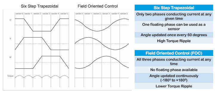
Figure 1. Difference between Trapezoidal and FOC
In designs that use trapezoidal control, the current is conducted only during two phases. During a floating phase, sensor readings are obtained. At this time, the values of the back electro-motive force (BEMF) can be monitored to deduce the rotor position. While BLDC motor designs typically have high torque ripple, this approach is simpler and less expensive to implement.
FOC implementations for PMSM motors conduct current in each of the three phases; each phase’s current, voltage and power is offset 120 degrees from the others’. This minimizes the torque ripple. Motor angle updates are continuous. This sinusoidal control primarily used for PMSM motors requires more elaborate electronic monitoring control circuitry. Control of an AC motor is essentially equivalent to controlling a DC motor using FOC.
As shown in Figure 2, torque is monitored and controlled by a Current Control Loop. Feedback from a tri-phase inverter is fed to a current-sensing circuit and relayed to the control loop to maintain precise torque levels. A Motor Position Module samples voltage and current values to provide angle and speed levels of the motor through a series of transform operations.
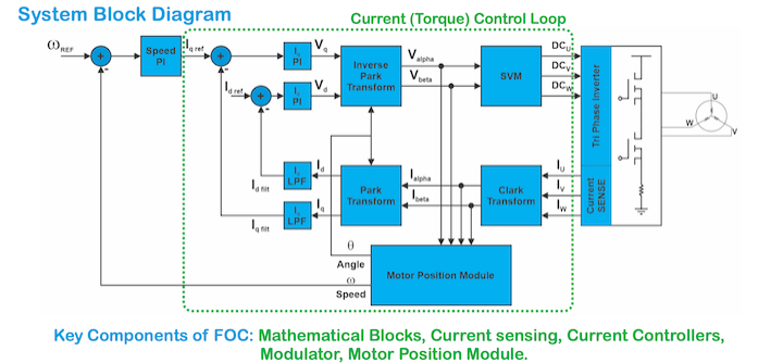
Figure 2. Fundamental components in a FOC-based implementation.
Other Key Takeaways
After the previous overview of FOC fundamentals, you should have a solid framework to better understand how firmware can be used to configure individual features. The Design Summit video offers a more detailed explanation of the typical process. It provides:
- A list of Qorvo’s FOC solutions, available IPs and a deeper dive into some of the features
- Step-by-step instructions for how to run a motor, including:
- Hardware set up
- Firmware Preparation
- Motor Parameters Identification – Auto-tuning
- Operating a motor from GUI or with a tuned motor parameter file (.xml)
- Debugging tools and more
The significant advances in motor control technology offer an array of opportunities for innovative product designs that capitalize on the efficiency, power handling and manageability of BLDC/PMSM motors. To learn more, go to Qorvo Online Design Summit: Field-Oriented Control for Tri-Phase BLDC/PMSM Motor Application.