Overcoming the Complexity Hurdle: Next-Generation SOI Antenna Tuning
February 1, 2023
Device Performance in a Complex RF World
At times, it appears technology is being developed and updated at the speed of sound – with things getting smaller, processing faster and changing our world in an instant. It is no different for the antennas of our mobile devices. Smaller mobile devices with many frequency bands make the antenna more complex. For engineers, this complexity is another hurdle to overcome. Meanwhile, technology development engineers continue to make incremental improvements with each generation – helping to meet more stringent system requirements – by making incremental technology improvements with each new generation. This blog post shows how silicon-on-insulator (SOI) technology improvements are making our devices perform better in a complex RF world.
For many years, the frequency bands in mobile devices have grown tenfold. For the past two decades or so, our mobile devices have included Wi-Fi, Bluetooth®, GPS and of course, cellular. Notably, since the introduction of 5G, the cellular and Wi-Fi bands have begun including higher frequency areas – above 3 GHz up and including 5-7 GHz. Today, we see the inclusion of ultra-wideband and mmWave. The latest mobile devices are equipped with antennas supporting all these bands – making things challenging for design engineers when optimizing antenna efficiency, power and range. To meet these design challenges, newer SOI technology developments must be used.

A Quick Look at Cellular Frequency Bands
One area affecting antenna design has been the cellular spectrum re-farming and acquisitioning. New bands have become available throughout the cellular spectrum and are helping to widen the overall bandwidth – with the additional benefit of increased capacity and data speed. Let’s take a closer look at each of these cellular low, mid and high bands:
- Low band – 600 MHz to 960 MHz
- Has a limited capacity with large area coverage and indoor penetration
- Mid band – 1.71 GHz to 2.17 GHz
- Is good for urban areas with increased capacity
- High band – 2.3 GHz to 2.69 GHz
- Has limited coverage or range with potential very high capacity
A Deeper Look at the Mid-to-High Band Cellular Antenna
As shown in Figure 1, this antenna structure supports the low, mid and high bands for cellular. Using the antenna PC board layout below, we compare two generational SOI technologies (previous generation and current generation). In this application, we use three antenna tuners; U2, U3, and U4 – to help tune the low, mid and high bands for coverage and range. Also shown in Figure 1 is an example block diagram of a 4-pole antenna tuner, similar to what is used in this application.
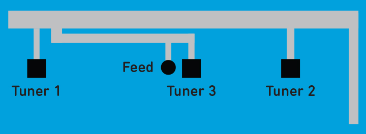
Figure 1: Low, mid and high band antenna structure.
This structure uses three antenna tuners that support the following bands.
- U2 supports mid-band and high-band tuning
- U3 supports low-band tuning
- U4 supports low-mid-high band
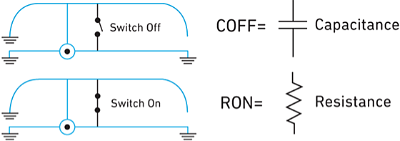
A Review of Switch RON and COFF
Aperture tuning primarily uses tuner switches and tunable capacitors. The main figures of merit for these switches are ON state resistance (RON) and OFF state capacitance (COFF), as shown below. For tunable capacitors, it is critical to have a wide range for tuning capacitance and a good Q factor (Quality factor). RON and COFF significantly affect antenna efficiency. RON's impact is greatest when the voltage is low; the impact of COFF is greatest when the voltage is high. Strategic placement of switches with low RON or low COFF optimizes tuning for different frequencies. (See also Mobile 5G Device Antenna Tuning Demystified blog post.)
In the OFF state, the COFF of an aperture tuner contributes to the capacitive loading on the antenna, lowering the resonant frequency. The higher the COFF of the tuner, the more the frequency shifts away from the antenna's natural resonance.
SOI Technology Comparison Data
To reduce generational PC board layout changes, new SOI antenna tuners remain pin-to-pin compatible. This helps keep engineering costs down for system designers.
Regarding the SOI technology improvements, RON, a measure of the switch ON-state resistance improved in the current generation. COFF, a measure of the switch OFF-state capacitance, also improved. Both figures of merit attribute to the overall antenna efficiencies we see in Table 1. In addition, the current generation improves on all target specifications for each low, mid and high bands.
Low, Mid and High Band Measurement Comparison Data
As you can see in Table 1, previous generation tuners struggle to meet efficiency targets in low band and high band. This is due in part because of the SOI COFF lossy parasitic capacitance. Using the current generation SOI reduces the COFF capacitance. This reduces signal leakage through each of the antenna tuner switch branches. Additionally, the current generation offers a slight reduction in RON. This improvement results in less switch resistance when a switch path is on. These RON and COFF improvements help switch isolation, reduce signal loss and increase efficiency.
The antenna for the SOI technology generations was tuned to optimize performance. Note that the delta in COFF between the antenna tuning products results in a frequency shift in antenna response which should be accounted for when tuning each band. Because of this frequency shift, the values of the matching inductors were adjusted to align the antenna resonance to the desired band.
As shown in Table 1 below, we see the overall system performance of the previous generation versus the current generation. The current generation shows a considerable increase in system antenna performance in each of the low, mid and high band areas. This further clarifies the SOI technology figure of merit increase.
| Low, Mid, or High Band |
Band | Efficiency Target (dB) |
Previous Gen Efficiency (dB) |
Current Gen Efficiency (dB) |
Current Gen Efficiency Improvement (dB) |
| Low | 13 | -7 | -7.1 | -6.6 | +0.5 |
| Low | 5 | -6 | -7.1 | 4.8 | +2.3 |
| Low | 8 | -6 | -7.4 | -4.2 | +3.2 |
| Mid | 3 | -5 | -3.4 | -3.1 | +0.3 |
| Mid | 2 | -5 | -4.6 | -3.6 | +1 |
| Mid | 1 | -5 | -5.4 | -3.8 | +1.6 |
| High | 40 | -5 | -10 | -5.1 | +4.9 |
| High | 7 | -5 | -5.6 | -4.7 | +0.9 |
Efficiencies in table for the Previous Generation to the Current Generation are average across band of interest.
Table 1: Comparison data of SOI/product generations
A common theme in new developments is that each generation update improves the previous design. This is no different with SOI technology. Each generational enhancement is passed onto products using this more recent technology creation. SOI has been around for some time and has had many technology enhancements. Making sure to use the latest cutting-edge technologies in your device design can be the difference between having a successful product or not. Just as using the current generation SOI will provide you with the needed antenna efficiency to meet end-product range, data speeds and capacity. For more detailed information on this described application, please feel free to contact us at technical support.
Have another topic that you would like Qorvo experts to cover? Email your suggestions to the Qorvo Blog team and it could be featured in an upcoming post. Please include your contact information in the body of the email.