True Time Delay: What It Is and How It Works
August 25, 2023
Steering in the Right Direction
Phased Array Antennas use phase shifters, true time delay, or a combination of both to point the summed beam more accurately toward the desired direction within an array’s steered angle. This blog post reviews both of these methods and how wider bandwidth antenna arrays are driving the use of true time delay in their system design. Also, see the latest article that explores the role of Time Delay Units (TDUs) and phase shifters in modern phased array systems, focusing on their use in radar, communication, and satellite applications.
Phased Array Antennas change the shape and direction of the radiation pattern without physically moving the antenna. The antennas are uniquely placed into a larger array using individual elements – summing them up to provide more gain performance and directing the signal within the array’s steering angle limits, as shown in the figure below.
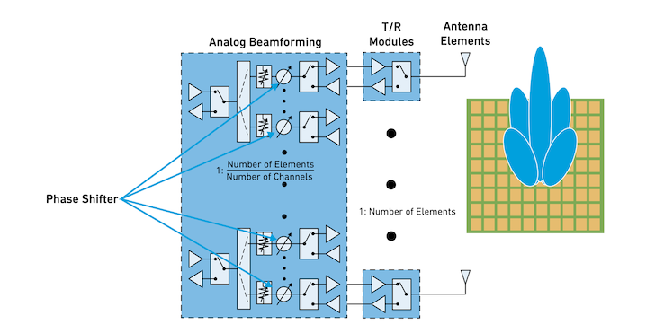
In today’s phased array systems, the bandwidth is increasing to expand their utility and flexibility. Wider bandwidth introduces system challenges that affect the phase shifting of the beam. Because of this trend, many AESA systems require true time delay to eliminate beam squint in larger bandwidth circumstances. We dig into this further in the following sections.
Background in Phased Arrays
The Phased Array Antenna size is inversely proportional to the operational frequency. Therefore, the higher the frequency, the smaller the antenna element spacing. The opposite is true for lower-frequency applications.
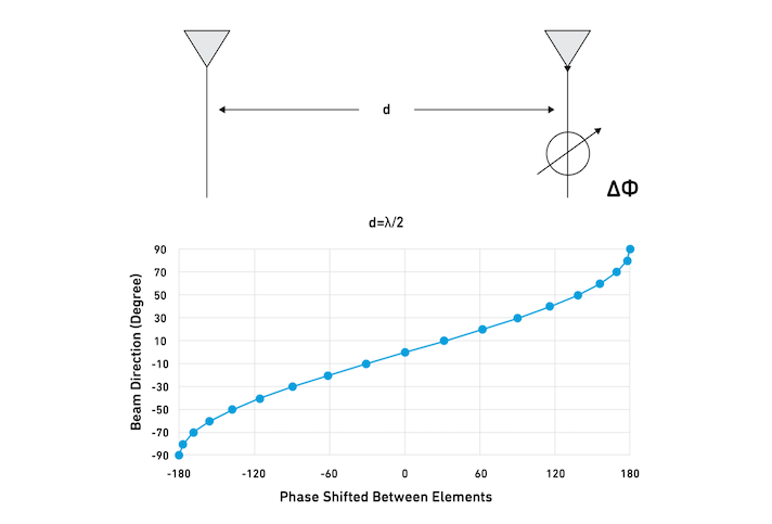
So, how is the beam steering enabled? Traditionally for narrowband arrays, we convert the desired signal delay at a given frequency using phase shifters. In the Phased Array Antenna, each antenna element can be fed with different phase shifters. Therefore, the beam direction of the array can be steered by changing the phase shift between each element to form a beam at the angle of interest.
For example, assume we have two antenna elements separated by distance “d,” as shown in the graph below. The phase shifts between these two elements, altering the beam direction. Using a phase shifter at the alternative antenna element, the beam can be steered to alter its direction and improve antenna efficiency.
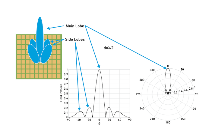
In the below image, we can see the steering of a waveform in the antenna array creates a main lobe at a given angle and minimizes the side lobes. We also see measured data of phase angle and field pattern of these lobes.
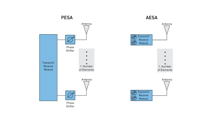
Below are two types of Phased Array Antenna systems that are commonly used.
- Passive Electronically Steered Array (PESA) – Uses a single transmit/receive module shared across all antenna elements.
- Active Electronically Steered Array (AESA) – Uses phased array antennas with transmit/receive modules dedicated to each element.
A Deeper Dive into AESAs
AESAs are the second generation of Phased Array Antennas. In AESAs, there are separate transmitters controlled by microcontrollers for each antenna element. These AESAs are more advanced than PESAs and can transmit several radio waves at various frequencies simultaneously in different directions.
As higher performance and higher resolution systems are developed, the bandwidth requirements for the waveform increase. This presents a problem for AESAs that traditionally steer the beam using phase shifters because the beam will squint as a function of frequency. Beam squint can be calculated using the following equation.
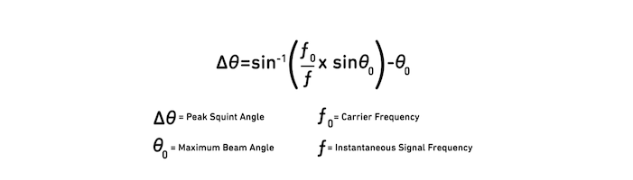
For these wide instantaneous bandwidth waveforms and narrow beam widths, beam squint can be enough to steer the beam off target resulting in poor signal quality, reduced accuracy and resolution.
AESA – Phase Shifters Versus True Time Delay
AESAs use phase shifters or a Time Delay Circuit, or a mix of both, to point the signal beam in the desired direction within the array’s steering angle limits.
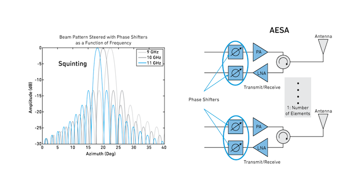
Phase shifters, as shown in the figure below, are used for directing the beams in Phased Array Antennas and help improve efficiency in narrowband systems. Phase shifters have had a wide market dominance and provide a fixed insertion phase difference between the two states. They are typically used in applications with lower bandwidth because wideband phase shifting is more difficult and often comes with a penalty of increased insertion loss and phase accuracy across the operational frequency bandwidth. The two states are only slightly different in time delay, differing in path length by less than a wavelength. Phase shifters steer the beam at each antenna element but do not provide true time delay. Without this true time delay, the beam distorts, or “squints,” over a larger frequency range as shown in the following graph. With newer, wider bandwidth array systems, beam squint has become more of an issue. True time delay units are used to mitigate this squinting effect.
Time delay units provide many wavelengths of phase shifting, and the phase shift is exactly proportional to the frequency. This allows the group delay difference between the two states to create a flat phase over the entire frequency bandwidth.
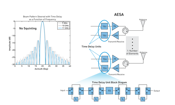
As you can see from the figure above, the time delay unit provides a noticeable benefit of squint reduction over the bandwidth frequency improving radar image resolution over the wider bandwidth.
True Time Delay MMICs
Time delay can be accomplished in many ways, e.g., coax, optical, microstrip, and strip-line. Electronic methods using MMICs are more popular due to their compact size and cost-benefit. Typical multi-bit time delay units include switches, time delay elements and equalizers to form both reference path and time delay pathways, as shown in the above figure. Overall delay range and delay steps can be generated by switching different path combinations. A reference line and delay element are typically created using different lengths of transmission lines. As the line length increases, so does the insertion loss and frequency. An equalizer is typically used to improve the overall time delay flatness over the frequency range.
Recent semiconductor developments and advances in modeling have helped to enable physically smaller delay circuits, which are useful in high-frequency array applications. Additionally, different semiconductor technologies like CMOS, GaAs and MEMs can be considered to help optimize performance requirements for some applications.
Key Takeaways
For today’s broadband array antenna applications, true time delay is required to mitigate squint. As we have shown above, understanding the differences in using TDUs and phase shifters or using them together is an essential part of AESA system-level performance. For more information about true time delay, read our latest article that explores TDU's role and phase shifters in modern phased array systems, focusing on their use in radar, communication, and satellite applications.
