Top Design Tips for the Automotive RF Front End
January 8, 2019
 Wireless automotive complexity is booming. Here’s how to
address it.
Wireless automotive complexity is booming. Here’s how to
address it.
Who could imagine the evolution of the automotive ecosystem? What used to be a simple mode of transportation has morphed into a vehicle with complicated computer systems connecting itself and us to the world around. Now it drives somewhat autonomously, communicates with the network and provides entertainment — and analysts predict these trends will only grow. According to McKinsey & Company, the number of networked cars will rise 30% per year for the next several years; by 2020, one in five cars will be connected to the internet. Strategy Analytics predicts the vehicle process and linear advanced driver assistance systems (ADAS) RF front-end (RFFE) market will be the largest, growing with a CAGR of 17% (2017-2022).
So how does an automotive RF engineer design a connected vehicle? Let’s first examine how
to overcome some of the biggest RF challenges in automotive design.
Today’s automotive landscape: A complex ecosystem of standards and challenges
Today’s vehicles have a lot of electronics connecting it to the world. For RF systems, this means the RFFE chains abound as vehicle manufacturers place more telecommunications in the car. The following diagram shows an example of a generic system.
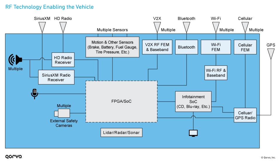
The changes in the automotive RF ecosystem bring several challenges for the RF system designer:
- Integrating many standards into the vehicle and sometimes into one module
- Coexistence concerns due to many of these standards being in close proximity
- Minimizing electronic component thermals
- Higher level of concern for power consumption, because all vehicle equipment works off the same battery power source
- Ensuring product components have long-term reliability
These challenges aren’t unique to the auto industry, and strategies to overcome them are
similar to other applications such as Wi-Fi connectivity and mobile devices. Here are some basic
design tips when selecting RF components for automotive:
- Use highly linear active or front-end devices.
- Use components that minimize insertion loss in the RFFE and decrease the overall RF link budget.
- Keep your eye on RFFE efficiency, current consumption and power dissipation.
- Use high-performance RF filters to minimize insertion loss, temperature drift and interference.
- Consider using components that integrate transmit, receive and filter functions in a single package.
- Use automotive-qualified products that adhere to IATF and IEC industry standards.
Let’s take a deeper dive into design considerations for RF coexistence, integration, antenna
design, thermal management, battery life and vehicle reliability.
Addressing RF coexistence
Users who are streaming video expect fast, reliable service in their automobiles, and streaming from the network and inside the vehicle are quickly becoming the standard. As a result, it’s important to minimize coexistence issues and reduce line loss when maintaining streaming services.
But maximizing coexistence between wireless bands and standards is challenging. If proper filtering isn’t used, there’s an increased potential for coexistence issues at the following frequencies:
2.4 GHz:
- Wi-Fi and cellular communications, like LTE Band 41
- Wi-Fi and Bluetooth
- SDARS (Satellite Digital Audio Radio Service) and LTE
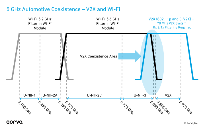
5 GHz:
- Wi-Fi and V2X (802.11p and C-V2X)
- V2X and U-NII (unlicensed national information infrastructure) bands, specifically U-NII-3
Related Blog Post: V2X in the Connected Car of the Future
Diagrams of the 2.4 GHz and 5 GHz spectrum show how crowded the bandwidths are for wireless technologies used in connected cars.
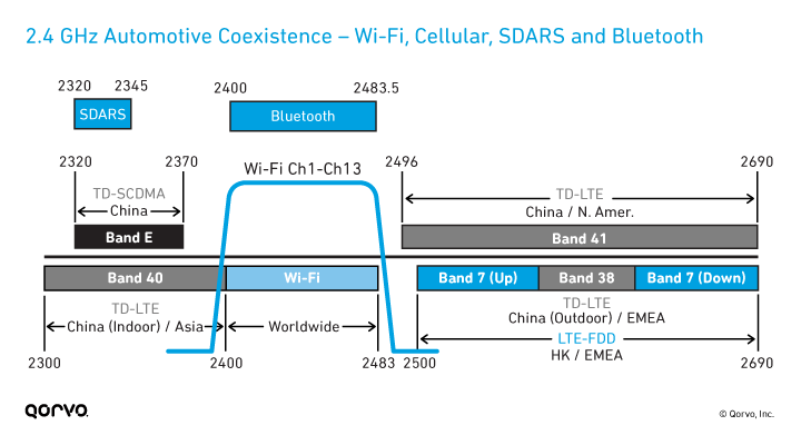
So, what’s the best way to mitigate these coexistence issues? Some best practices are to use high-performance RF filters and highly linear active devices in your design.
- Filters reduce the out-of-band interference between radio signals.
- Coexistence filters mitigate potential desensitization for transmitted signals.
Today’s vehicle communications support many transmit and receive paths between the
antenna(s) and transceiver, and isolation of these paths requires filters. These filters must:
- Provide isolation from coexisting frequency bands.
- Have low insertion loss to minimize transmit power consumption.
- Optimize receiver sensitivity.
Integration is important
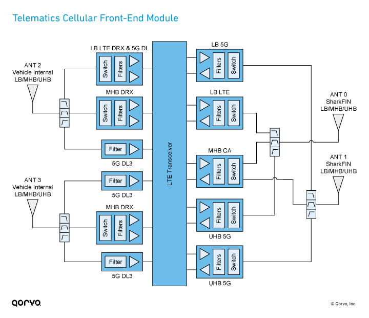
The mobile phone industry has already made the transition from discrete components to highly integrated system modules. As cars pack more connectivity into the same overall vehicle footprint, automotive manufacturers must also make this same transition. Integrating more functions into a front-end module (FEM) or filter modules helps to simplify the RF design, as shown in the next block diagram.
(A bonus? Integrating the right filter technology inherently helps manage the coexistence issues we discussed earlier, as well as thermal challenges.)
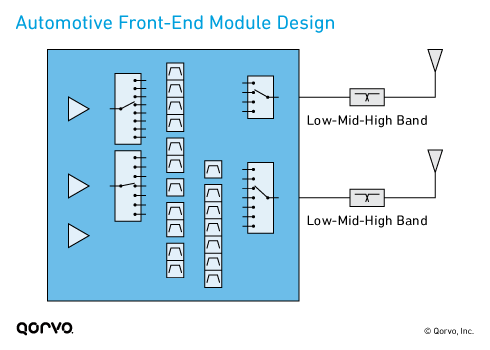
Vehicle engineers were once only concerned with GPS and Bluetooth, but now they must design for new wireless standards like C-V2X and, in the future, 5G New Radio (NR). Designers must learn all the technology shown in the block diagram below, while incorporating it into their automobile designs. The most likely approach will use mobile phone technology as a springboard.
Qorvo engineers created RF Fusion™ to help our
customers leverage an integrated solution, which effectively reduces design complexity and enables
faster time to market. Many of these complex modules include embedded filters, which further
reduce the RF complexity and the overall link budget.
Antennas and the RFFE
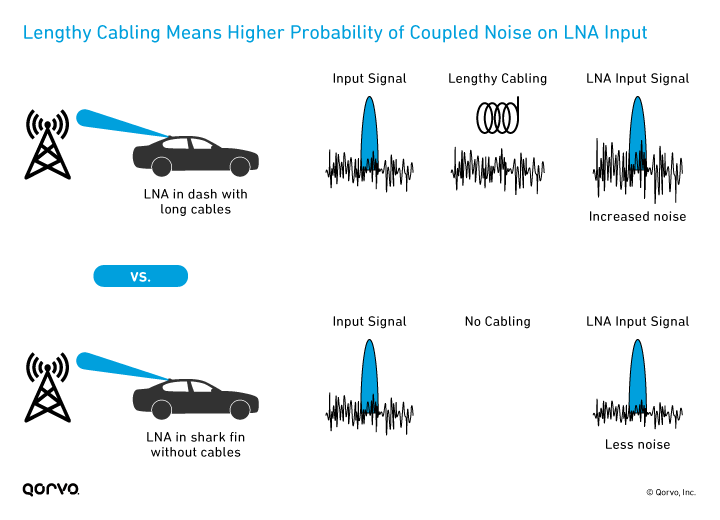
Picture a shark fin antenna that’s connected to a cable, which then runs to the low noise amplifier (LNA) elsewhere in the car (usually in the dashboard). While it’s common practice for cabling to be used in traditional vehicle manufacturing, lengthy cabling can cause insertion loss between the antenna and the RFFE (increasing the link budget). This also increases noise figure (NF) on the LNA input, especially in cellular and Wi-Fi scenarios, and degrades the signal and receiver sensitivity. If the antenna can receive a lower power level, its sensitivity improves.
One way to counteract this is to have the antenna and RFFE components in the shark fin on the roof, as close to the signal input as possible and before any cabling. By integrating the RFFE close to the antenna, you can minimize the NF and improve signal performance — and keeping NF low also helps receiver sensitivity.
The same approach can work to improve the transmit function of the antenna too. Reducing the
cabling and putting the power amplifier (PA) closest to the antenna will help reduce
insertion loss and power. If you need more power on the transmit side before sending the signal,
you can also use a compensator in the shark fin to amplify the signal and compensate for the loss
and link budget caused by the cable lengths.
Thermal management
In the vehicle, one of the key critical design challenges is temperature, whether inside the vehicle or in the outside environment. Vehicle products get hot, and these temperature increases affect system-level RF tuning and performance.
All wireless connections and electronics still live within the same small vehicle footprint. This means increased radiated heat in a confined area. Thermal heat also affects reliability, which can compromise safety features in the automobile.
When trying to mitigate thermal issues, key parameters to keep your eye on include:
- RFFE efficiency
- Current consumption
- Power dissipation
Some thermal dissipation methods available to designers are conduction and convection cooling, but these are
of limited use in a car. Further complicating this thermal challenge are the small product form
factors. The following techniques can help manage RF issues related to heat:
- Use PC board layout files and evaluation boards from component manufacturers. Your best bet is to request and use the manufacturers’ design, because their layout is optimized for heat dissipation and thermal efficiency.
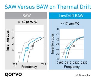
- Use RF filters with minimal or no shifts over temperature. As shown in the next image, filters drift to the left or right due to temperature changes. For automotive systems, it’s important to use temperature-compensated filters with outstanding temperature stability, low insertion loss and a high Q factor, such as Qorvo’s BAW technology, to help counteract issues related to heat (as well as coexistence). On average, BAW technology is 50% more temperature stable than SAW.
- Use highly linear front-end products. PA efficiency is attained by using highly linear front-end products, which optimizes system efficiencies and creates less heat. It’s important to keep insertion loss minimized in the RFFE — especially when running hot. Poor RFFE performance affects current draw on the entire automotive system and makes the system’s processor work harder. In turn, this causes thermal heat, system degradation and draw on the vehicle battery.
Battery life
In 2017, the J.D. Power Vehicle Dependability Study reported that for the first time, battery failure was among the list of top ten problems facing car owners. According to their findings, the battery is the most frequently replaced component that isn’t related to normal wear and tear — and they’re replaced in 6.1% of 3-year-old vehicles, an increase of 1.3% from 2016. They determined that the increased current draw from many new, complex on-vehicle electronic systems (such as infotainment, smartphone connectivity, voice recognition and keyless entry) were dragging down battery life.
One example is the vehicle key fob to unlock and start a car. Car owners use this technology for convenience — but it can drain the car battery. If the key fob is kept within close proximity or inside the vehicle, the transmitter and receiver continue to communicate, pinging the vehicle. Testing shows that having the key fob close to the vehicle drains the battery faster than if it’s left outside the car.
As new wireless and wired technologies find their way into the automobile, it’s important to do the following to extend battery life:
- Target device solutions with low power consumption.
- Understand RFFE power consumption during both idle and running time.
- Use filters that have minimal or no shift over temperature.
Reliability and long-term performance
The automotive electronics sector provides solid revenue growth prospects for RF semiconductor suppliers. Innovations in applications like ADAS, electric vehicles, human-machine interface (HMI) and connected infotainment are driving increased semiconductor content, and automotive engineers must get the RF and other subsystems working together seamlessly. These semiconductors also need to meet the stringent reliability requirements established by the automotive industry.
It may be tempting to use a commercial part instead of a dedicated, auto-qualified product. But selecting a product designed specifically for automotive applications and that has passed IATF and IEC certification tests can help ensure your RF system will work over the long haul.
Related Blog Post: Automotive Quality Standards 101: What Qualification Really Gets You
The drive to get ahead
Automotive makers are evolving at a record pace to meet consumers’ desire for wireless
connectivity on the go and more-autonomous cars. As this evolution occurs, RF technology inside
and outside the vehicle will become more prominent. By using highly integrated RF components and
springboarding off innovative smartphone technology, automotive manufacturers will have a leg up
on developing the connected autonomous vehicle in our future.
Connected Car For Dummies®

Take a look inside the connected vehicle in a 5G world, in our free e-book.
Have another topic that you would like Qorvo experts to cover? Email your suggestions to the Qorvo Blog team and it could be featured in an upcoming post. Please include your contact information in the body of the email.
